
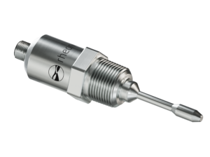
Ceramic Slurry Viscosity & Density Control
Every shell layer, every surface finish, and every dimensional tolerance traces back to one thing: how well the slurry’s viscosity and density are controlled throughout the shift.

In investment casting, the ceramic slurry determines the part quality. The whole game is keeping its viscosity and density constant continuously, and that is exactly where the flow cup or lab instruments fall short.
Moving from manual Zahn cups to automated inline monitoring with the Rheonics SRV, SRD, or SlurrySense sensors prevents slurry defects such as cracking and spalling, also compensates for evaporation, and keeps structural parameters within strict limits.
The result is a direct improvement in production yield, final parts quality, and Overall Equipment Effectiveness (OEE) in every batch.
Video 1. SlurrySense: Self-Cleaning Precision for Investment Casting Applications
Process context
Investment casting builds precision metal parts by dipping a wax pattern into a ceramic slurry, again and again, to build a shell around it. Then, the wax is melted out, and the shell is fired to strength. Finally, molten metal is poured into the cavity the wax leaves behind to create the piece. Everything that matters about the finished part (surface finish, dimensional accuracy, shell strength, and defect rate) is decided in the shell room, and the single most important control variable there is the viscosity of the ceramic slurry.
The slurry’s flow characteristics set how much material each dip picks up and how evenly it coats, which in turn sets the thickness and quality of every layer of the shell. Viscosity measurement is the most widely used slurry control test in the industry because it is the most direct, actionable read on whether the slurry will build a good shell or not.
However, a working slurry will not hold still. Its viscosity depends on the filler-to-binder ratio as well as on ageing time. In service, the slurry viscosity drifts continuously due to:
– Water evaporation from the open dip tank
– Temperature changes
– Slurry ages
The viscosity and density rise as water is lost. This is exactly why foundries have long tracked density, viscosity, and the binder ratio together on a slurry control chart, and restored both viscosity and density by adding water.
Density is therefore not a separate concern but a partner to viscosity: it is a direct indicator of solids loading and blend, and at constant binder ratio it moves in lockstep with viscosity as evaporation concentrates the slurry. Measuring both gives a complete, redundant picture of the slurry’s state. The control problem, then, is to catch that continuous drift and correct it before it shifts the shell, in a fluid that is abrasive, ages, and, as it happens, fouls the very instruments meant to measure it.
In depth: Ceramic Slurry Characteristics
Ceramic dip slurry is controlled on two coupled properties. Viscosity drives coat pick-up and surface quality and is the industry’s central slurry test. It is read traditionally as a flow time on a Zahn or RW cup, with prime coats around 8–12 s (No. 4 Zahn) and back-up coats around 17 s (No. 5), equivalent to the low thousands of centipoise.
Density tracks the refractory-to-binder loading (% solids); at a fixed binder ratio, density and viscosity rise together as water evaporates.
Reading both continuously fingerprints the slurry and separates a genuine ageing or gelation change from a simple dilution or top-up.
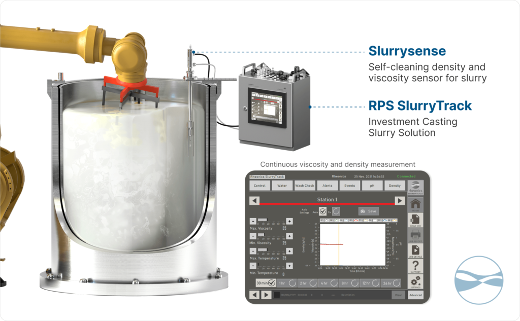
Figure 1. Continuous data from Ceramic Slurry tank
The measurement problem
The traditional measurement is the Zahn or RW flow cup: viscosity read as the number of seconds a slurry takes to drain through an orifice. It is cheap and familiar, but it is manual, intermittent, and operator-dependent, and it is not particularly accurate or repeatable.
Crucially, it cannot give the continuous, repeatable signal that real process control needs. It is a spot check, taken when an operator has time, not a live trace. Because the accuracy with which a foundry can actually hold a slurry viscosity is capped by the accuracy and repeatability of its measurement, the flow cup limits control quality at its source. A slurry can only be held as tightly as it can be measured, and an intermittent, operator-dependent reading does not support tight control.
There is a second, harder problem unique to this fluid: ceramic slurries foul instruments aggressively. Deposits build on any surface left in the tank, and tenacious build-up cannot be cleared by flow changes, rinsing, or temperature alone. A fouled probe slowly stops reading the live slurry and starts reading its own coating. This silently corrupts the very continuous-monitoring benefit an inline sensor is installed to provide.
The shell room is also an unforgiving environment for instrumentation: abrasive slurry, frequent handling, and tanks that are typically rotating to keep the slurry homogeneous. An instrument here has to be robust, deposit-resistant, and stable without routine recalibration, or it becomes a maintenance burden the foundry will quietly stop trusting.
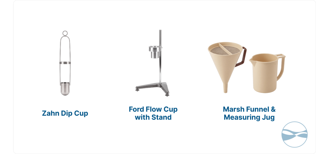
Figure 2. Different cup variants in the industry.
Rheonics solution
Rheonics replaces the flow cup with inline measurement built on a balanced torsional resonator. The SRV outputs viscosity and temperature; the SRD outputs density, viscosity, and temperature together. Both measure continuously and in place, with no moving parts and no in-service recalibration. The locked signal bands are ±1% of the reading on viscosity and ±0.001 g/cm³ on density, which is the repeatable, continuous signal the flow cup cannot provide.
The differentiator that makes this work in ceramic slurry specifically is self-cleaning. Based on the SRV and SRD, Rheonics has created the SlurrySense with CleanWave™, which is a self-cleaning probe whose action keeps the sensing element free of the tenacious deposits that would blind a conventional probe. Without self-cleaning, continuous monitoring of a fouling slurry degrades as deposits build; with it, the measurement the control loop depends on stays trustworthy shift after shift.
The sensors are commonly installed in the rotating dip tank, where their readings register changes in spin velocity, the insertion of moulds, evaporation, etc. This is a sign they are tracking the live tank state rather than a settled sample.
Additionally, an integrated slurry tracking and predictive system (SlurryTrack) applies those readings to hold slurry viscosity and density constant through shell building despite evaporation, temperature swings, and ageing. It can control diluent addition by opening and closing the solvent valves, as evaporation concentrates the slurry and flags gelling in real time. This is the heart of Foundry 4.0: smart precision casting driven by a live data signal rather than periodic manual checks.
Together, self-cleaning, continuous dual-parameter measurement and integrated control turn the shell room’s central variable from a periodically-sampled unknown into a held setpoint.
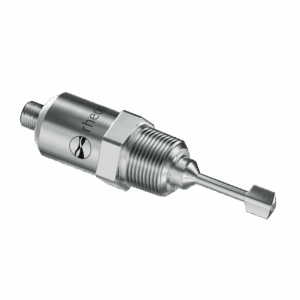
Rheonics SRD
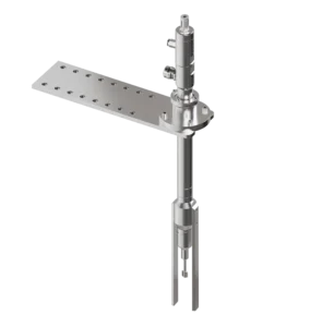
SlurrySense
Installation & integration
The sensor probe is installed in the slurry open dip tank from the top using a Mounting Kit Accessory (MKT1, MKT2, or MKT3). The sensing element is submerged in the live slurry and positioned to read the mixed bulk.
For ceramic slurry applications, the self-cleaning SlurrySense with CleanWave™ variant is used to avoid fouling tendency that would otherwise blind a static probe, which is common in most ceramic-slurry duties.
The sensor measurement feeds the integrated tracking-and-control approach (provided by Rheonics or by the customer itself), which holds viscosity at setpoint by managing diluent addition against evaporation and raises alarms on gelling or out-of-band excursions. Output integrates with the foundry’s existing control infrastructure over different compatible communication protocols such as PROFINET, PROFIBUS, 4-20 mA, HART, etc., so the slurry signal joins the rest of the shell-room data for automation and traceability; see all the compatible communication protocols here.
Commissioning establishes the target viscosity and density band for each slurry at its working temperature and binder ratio, reproducing the foundry’s existing control-chart targets as live setpoints; no in-service recalibration is required.
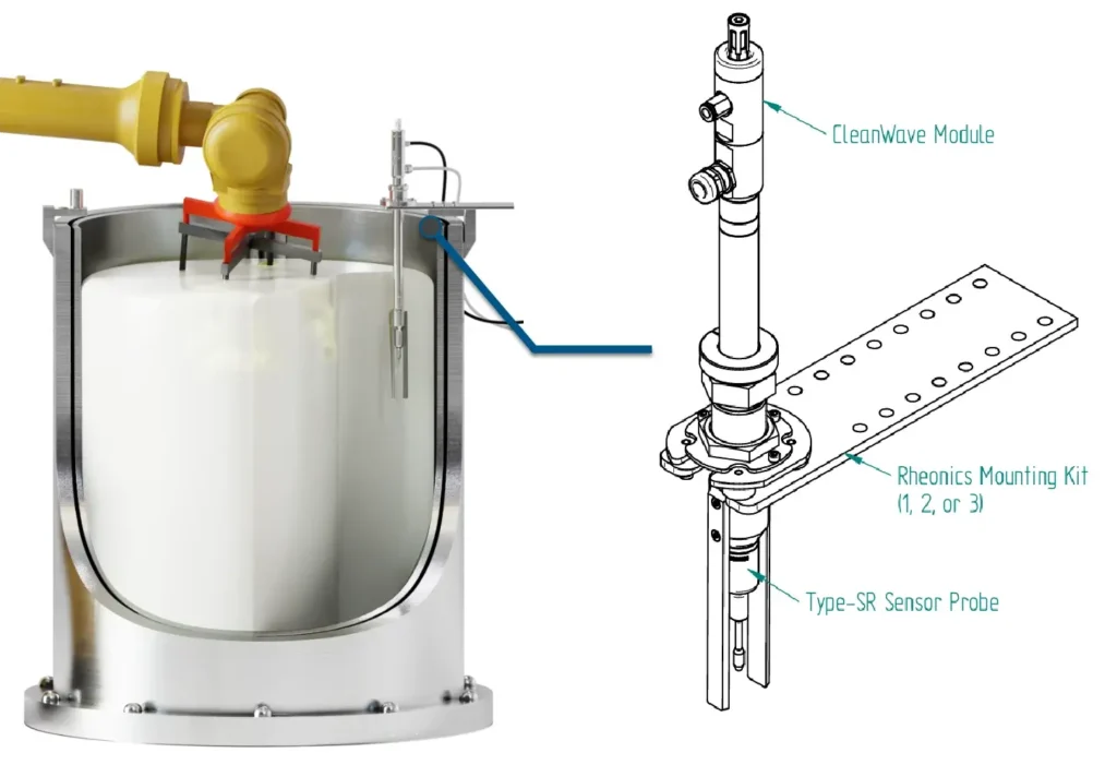
Figure 3. SlurrySense Installation in an Open Slurry Tank
Signal behaviour
On a continuous inline trace, the slurry’s behaviour through a shift is fully legible, thanks to the feedback from the SlurrySense sensor.
Evaporation from the open tank concentrates the slurry, so viscosity and density climb together at constant binder ratio; a diluent addition brings both back down; the onset of gelling shows as a characteristic departure. What was a sparse column of flow-cup numbers in a logbook becomes a continuous curve a controller or an operator can act on.
Business value
The direct value is a slurry held to the same viscosity and density for the first mould of the shift and the last.
Holding the slurry at setpoint despite evaporation, temperature and ageing means uniform coats, fewer defects and less scrap, because the variability that periodic flow-cup control allowed between checks is removed. Self-cleaning converts that from a theoretical to a sustained benefit: in a fouling slurry, a continuous measurement is only valuable if it stays accurate, and SlurrySense with CleanWave™ keeps the loop seeing the true slurry state shift after shift rather than degrading as deposits accumulate.
Replacing the flow cup also frees operators from repetitive manual measurement and from manual control-chart keeping, and it raises the achievable control accuracy because the measurement beneath the loop is continuous and repeatable rather than intermittent and operator-dependent. And because the slurry state is now a continuous digital signal, it integrates with the foundry’s control systems for automation and produces a per-shell traceability record. This record is increasingly demanded by aerospace and medical casting customers, who want evidence of the conditions each part was built under.
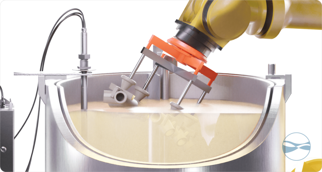
Figure 4. Dipping wax pattern in Ceramic Slurry
Why Rheonics?
| What matters | Rheonics SRV/SRD | Typical alternative |
|---|---|---|
| Mounting & vibration | Balanced torsional resonator technology which makes the sensor insensitive to mounting position and pipe vibration | Many inline/lab instruments are mounting- and vibration-sensitive |
| Properties measured | Real time Density, viscosity and temperature from one probe (SRD); wide-range inline viscosity (SRV) | Often one property per instrument |
| Maintenance | No moving parts; easy to clean; no routine recalibration | Other measurement methods like the cups or lab instruments may need cleaning, recalibration or licensing |
| Hazardous areas compatibility | Can be Ex Certified for Zone 0, 1, and 2 or C1D1, C1D2. | Varies by device |
| Continous measurement | Real Time inline measurement in the direct process | Offline measurements |
General product characteristics; confirm exact specifications and certificates for your configuration with Rheonics.
Article Summary Key points
- The ceramic slurry sets layer thickness, surface finish, strength and defect rate; viscosity is the industry’s central slurry control test.
- Working slurry viscosity drifts with evaporation, temperature and ageing; at constant binder ratio, density and viscosity rise together as water is lost.
- The Zahn / RW flow cup is intermittent, operator-dependent and imprecise, it caps how tightly viscosity can be held.
- Inline SRD and SRV gives continuous density, viscosity, and temperature values, feeding a tracking-and-control loop that corrects drift in real time.
- SlurrySense with CleanWave™ self-cleaning keeps the probe deposit-free in fouling ceramic slurry, otherwise without it, continuous monitoring degrades as deposits build.
Frequently asked questions
Why measure both viscosity and density?
Viscosity drives coat pickup and surface quality; density tracks the refractory: binder loading (% solids). Together they fingerprint the slurry and distinguish a real ageing/gelation change from a simple dilution or top-up.
How does density help control the slurry?
Density reflects the solids loading, so a density change flags evaporation (concentrating the slurry) or over-dilution from binder top-up, before it shows up as a coat defect.
Does inline measurement replace flow-cup or any other offline/lab method?
Not necessarily. Flow cup or any other offline/lab method can remain in-room as reference values, by performing quick tests from time to time. Inline viscosity and density are the continuous control signals for control. So both options can co-exist together.
Across the Rheonics Knowledge Centre
Related content