Estimating effective shear rate of inline process viscometer SRV and density meter SRD
Rheonics Type-SR sensors are inline instruments to measure real-time viscosity and density of a fluid, as well as temperature and derivatives from these values. Rheonics offers the SRV process viscometer to measure viscosity and the inline density meter SRD for density and viscosity values of a fluid. Both sensors probes are compact, light-weight and hermetically sealed, making them suitable for all industrial processes involving liquids.
Both SRV and SRD sensors are based on balanced torsional resonator (BTR) technology. Both sensors measure and output measurements of viscosity for the fluid they are in contact. For Newtonian fluids, you get the same viscosity irrespective of the instrument used. However for non-Newtonian fluids, that is not the case and different instruments measure different values of viscosity – this is often not due to inaccuracy of the instrument itself but due to the shear dependence of viscosity and the fact that different instruments make measurement at different shear rates.
Due to this shear dependence of viscosity for non-Newtonian fluids, and to enable some comparison between different viscometers (often between process viscometers like SRV and lab instruments like rotational viscometer or rheometer), it is desired to understand the effective shear rate at which SRV or SRD is making the measurements. The analysis below mentions SRV but is equally valid for the SRD.
1. How does the process viscometer SRV or density meter SRD operate?
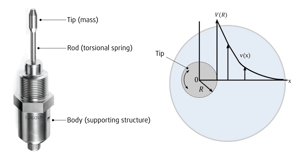
The SRV sensor’s sensing element consists of a rod and a mass attached to its end, this rod and the tip are circular and cylindrical. The other end is connected to the body that contains the transducers for excitation and sensing.
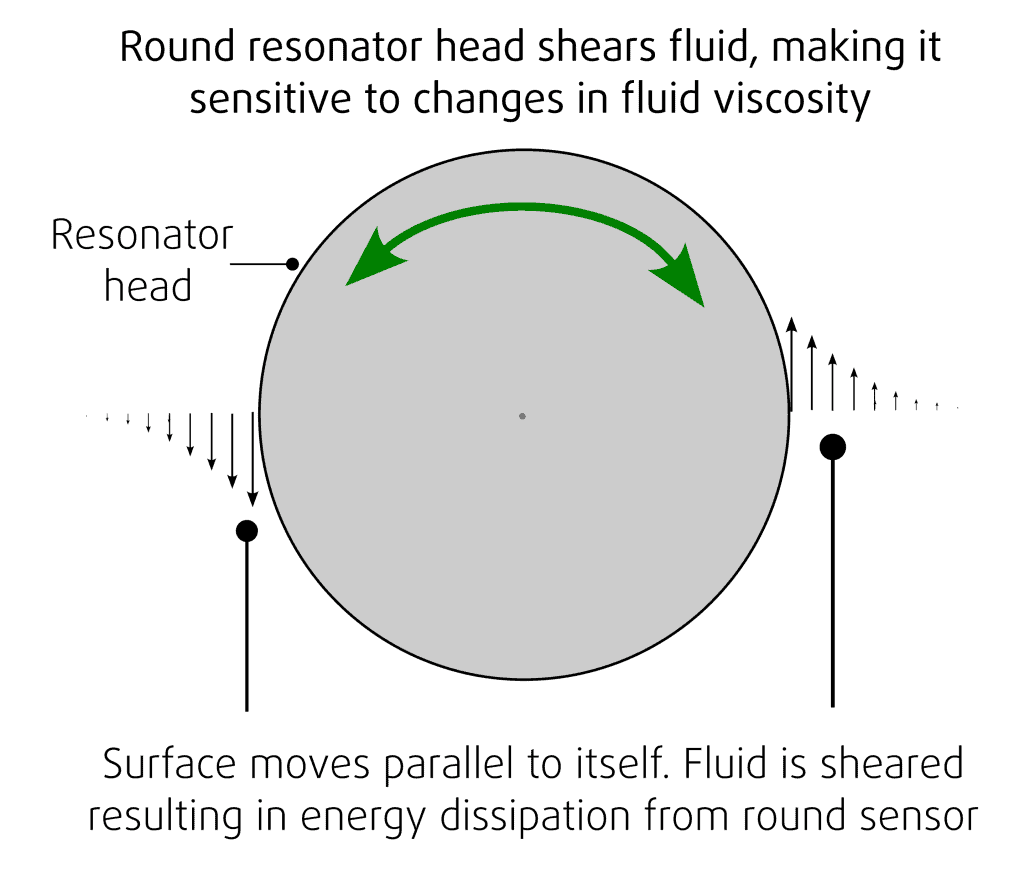
The sensor vibrates in torsion, torsional resonators are more stable and better isolated from their mechanical environment. Torsional resonators that are cylindrical vibrate parallel to their own surfaces. They are influenced by shearing forces and are therefore primarily sensitive to dissipative forces (viscous damping) rather than mass loading effects (also often referred to as inertial damping).


2. Why is the shear rate relevant for process viscometer?
Viscosity of a non-Newtonian fluid can change depending on the shear rate it is subjected to. This means that a single viscosity value can’t be associated with this kind of fluids under all states (eg. static, flowing at different speeds).
Laboratory viscometers often allow users to change the shear rate or rotational speed at which viscosity is measured. Rheonics SRV and SRD have a shear rate usually much higher than those for lab instruments and users cannot change it.
It is possible to have a qualitative idea about the range of shear expected for the SRV viscosity sensors and calculations are shown in this article. This helps qualify (and to some extent quantify) conditions at which viscosity is being measured and correlate readings with other instruments.
However, actual correlations between shear of Type-SR viscosity measurements and other lab instruments are mostly empirical and may not meet the qualitative estimation. The estimated shear rate may not exactly match the viscosity value from a rheometer. Consider that Rheonics sensors are process control devices more than just a viscosity sensor with emphasis on extremely high repeatability, and reproducibility of measurements with an unmatched resolution (often 10-100X higher than lab instruments).
3. Shear Rate estimation of oscillatory process viscometer
There are two parameters that are the most important for the shear estimation which are velocity amplitude and the boundary layer thickness. It is necessary to calculate the following parameters.
The shear stress is given by:

Equation 1: Shear Stress.
For a Newtonian fluid, η is a material constant characteristic of the fluid, ∂v/∂x is the shear rate in the fluid Applying the Navier-Stokes equations, solving under periodic, uniaxial conditions, the solution for the velocity amplitude is:

Equation 2: Velocity Amplitude
Where:
- x: distance from the sensor wall
- V: velocity amplitude at the sensor surface, R is radius of the tip
- δ: is the boundary layer thickness
- i: is square root of -1
The boundary layer thickness can be found with the equation:

Equation 2: Boundary Layer Thickness
- η: dynamic viscosity
- ω: angular frequency
- ρ: fluid density
By considering that at x=2δ the velocity drops to 13 % of the value at the sensor surface. The shear rate γ=∂v(0)/∂x at the surface of the sensor (x=0) follows:

Equation 4: Shear Rate
Where the velocity amplitude V(R) (5) is given by:

Equation 5: Velocity Amplitude
- R: Distance from vibrational axis to sensor surface
- φ: Angular vibration amplitude.
The tip from the SRV performs a sinusoidal rotational vibration φ about its axis of symmetry.

Equation 5: Sinusoidal Rotational Vibration
For the SRV, the velocity V(R) is approximately 50 mm/s and Frequency is 7500 Hz → ω=2π x 7500
The parameter V(R) is independent of viscosity, but the boundary layer thickness of the fluid δ increases. The following graph demonstrates the shear rate vs viscosity behavior and shows shear rate variation with both viscosity and density of the fluid under investigation.

Applications of shear rate estimates of process viscometer in Industrial processes
The effective shear rate of an oscillatory viscometer is the shear rate that the fluid experiences during measurement. It is important to estimate the effective shear rate of an oscillatory viscometer to compare the results obtained from different viscometers and to design industrial processes involving non-Newtonian fluids.
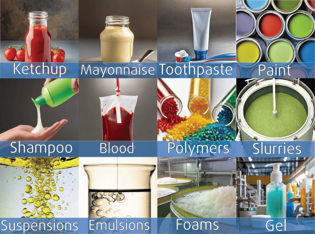
Vibrational process viscometers like the SRV and SRD are widely used to measure inline real-time viscosity of non-Newtonian fluids in a variety of industries, including food processing, cosmetics, and pharmaceuticals.
Some examples of non-Newtonian fluids that are commonly measured using vibrational process viscometers are shown on the left.

Sensor Technology, Working principle and Applications
Viscometers
Density Meters
