Competitive Analysis of Rheonics viscometers, density meters and HPHT density and viscosity meters built on the vibrational sensor technology.
Rheonics sensors employ patented balanced torsional resonators.
Temperature, pressure and external vibrations offer the greatest challenges to accurate and repeatable density and viscosity measurement. Rheonics balanced torsional resonators together with proprietary 3rd generation electronics and algorithms makes our sensors accurate, reliable and repeatable under the harshest operating conditions.
- Ultra-stable resonators, built on a foundation of more than 30 years experience in materials, vibration dynamics and fluid-resonator interaction modeling that add up to the industry’s most robust, repeatable and accurate sensors.
- Sophisticated, patented 3rd generation electronics to drive our sensors and evaluate their response. Great electronics, combined with comprehensive computational model make our evaluation units the fastest, most accurate in the industry.
At the heart of every Rheonics sensor is a resonator. Rheonics sensors are always in tune with the fluids they’re measuring!
The resonator vibrates in the fluid; the fluid influences the resonator’s vibrations. By measuring its effect on the the resonator, we can determine the fluid’s density and viscosity.

The Torsional Advantage
Many types of fluid sensors use lateral vibrations. Vibrating wire viscometers, for instance rely on the displacement of the wire perpendicular to its long axis. Flexural tuning fork resonators have two tines that vibrate as cantilever beams, with motion perpendicular to the plane of symmetry of the tuning fork.
In general, sensors that vibrate laterally are harder to isolate from the structures in which they are mounted. Mounting forces, the mass of the mounting structures, and even temperature can influence the response of the resonators in ways that are unpredictable, and therefore influence the repeatability of measurements.
Rheonics sensors vibrate in torsion. Their active elements twist about their own axes, rather than vibrating laterally. Torsional sensors are easier to isolate from the structures in which they are mounted. They are also less disturbed by ambient vibrations than are lateral resonators
Inline Process Viscometers Comparison
| Torsional Balanced Resonator Viscometer (Rheonics SRV) | Tuning Fork Viscometer | Vibrational Viscometer | Unbalanced Torsional Viscometers | |
|---|---|---|---|---|
| Viscosity Range | 0.3 – 50,000 mPa.s | 0.5 – 1000 mPa.s | 1 – 25 mPa.s and 1 – 50 mPa.s | 1 – 5000 mPa.s (some claim higher) |
| Viscosity Accuracy | 1% of actual | 0.2 cP or 10% of Full scale | 2% of actual with min. 0.5 mPa.s | 5-10% of actual |
| Viscosity Repeatability | within 0.5% | within 0.5% | No data. | Claimed within 1% (customer feedback suggest worse) |
| Flow rate | No influence. | Installed in a recess in the pipe. | No influence. | No influence. |
| Fluid type (newtonian/non-Newtonian) | Newtonian & non-Newtonian Stable, repeatable in non-Newtonian fluids | No data on non-Newtonian fluids. Low usage in other viscosity applications. | No data on non-Newtonian fluids. No data on any other application besides marine fuel. | Application notes and customer data exists for use in non-Newtonian fluids. |
| Pressure rating | 0 to 3000 psi (200 bar). 2.5X safety factor. | 0 to 3000 psi (200 bar). 1.5X safety factor. | 15 bar. | 50 bar |
| Pressure influence | Fully compensated. No need for calibration. | Significant, not compensated. | Not compensated. | Not compensated. |
| Temperature rating Temperature calibration | -40 to 200 °C // 0.1°C thermal stability. Small mass of sensor. Isothermal conditions enable excellent viscosity accuracy. No difference in factory vs. field conditions. | -50 to 200°C No inbuilt temperature sensor. Less than 1°C stability. Huge mass of sensor. Needs external temperature input. | Max. 180 °C 1°C stability. Large mass of sensor. For marine fuel viscosity monitoring, meets specs. Not suitable for other applications. | Typical 150 °C. Low temperature stability. Fast changing fluid temperature leads to high errors in measurement. No co-located temp. sensor. |
| Installation requirement Instrument Size | Needs a 3/4” instrument port for any pipe diameter. Smallest inline process viscometer sensor in market (1” x 3”) | Needs well defined flow regime. Needs a large adapter. Large (2” x 10”) | Vulnerable to pipe noise and external vibration. Large (2” x 8”) and heavy (1 kgs) | Various mounts available. Large size. |
| Price | $ | $ | $ | $ - $$ |
| Installation cost | 0 to Low $ | High | High | Medium to high |
| Maintenance | Zero | Coating failure and deposits on sensor. | Coating failure and deposits | Frequent calibration & maintenance. |
| Lifetime cost to customer | $ | $$$ | $$$ | $$$ |
| Typical process issues | Deposits on the sensor. | Significant wall effect, requires special adapters for each flow condition. Not suitable for other viscosity applications. | One trick pony aimed at Fuel viscosity monitoring. Not suitable for other viscosity monitoring applications due to limited range and accuracy. | Large size causes temperature variation leading to high measurement errors. Needs significant process deployment due to variation between instruments. |
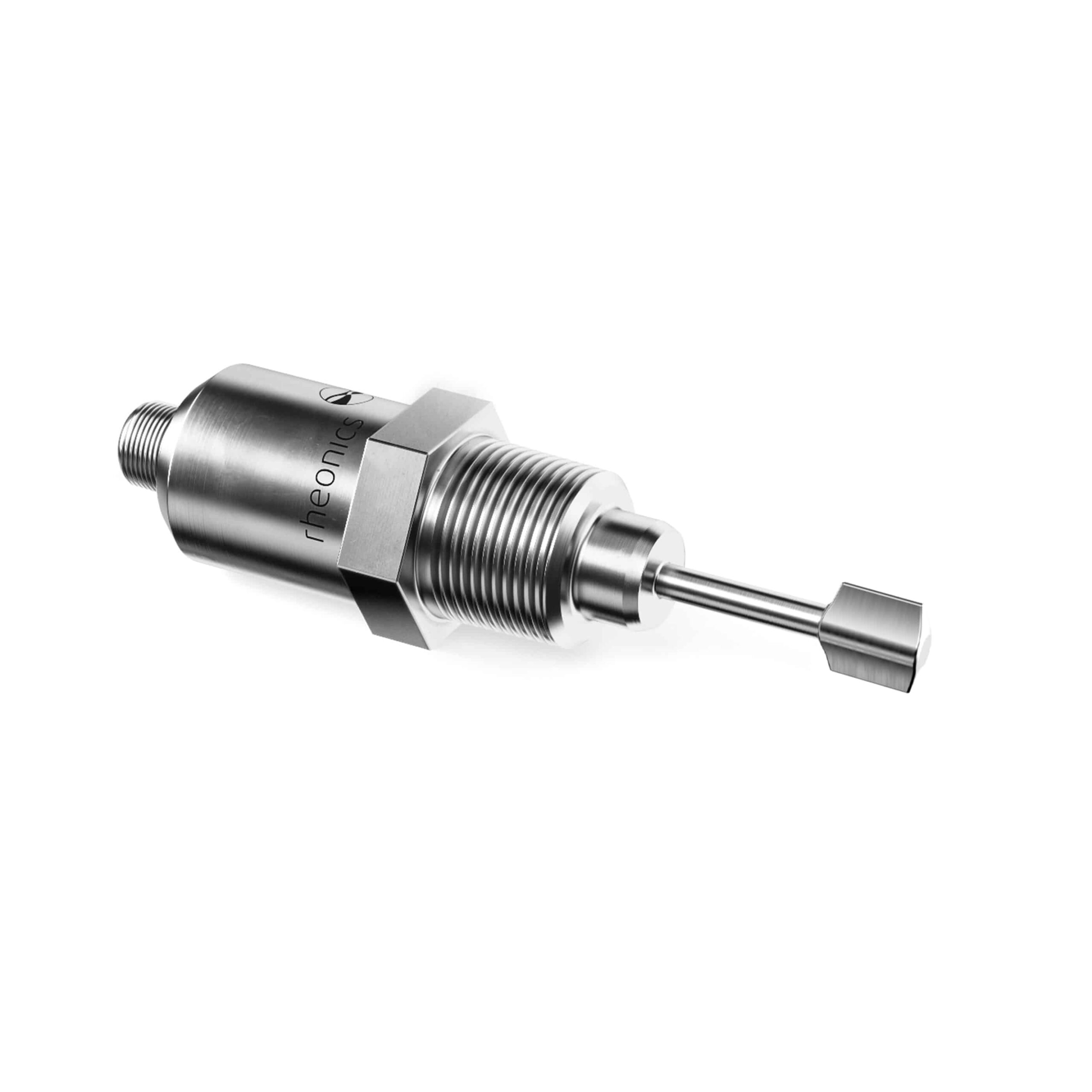
Rheonics Inline process viscometer - SRV
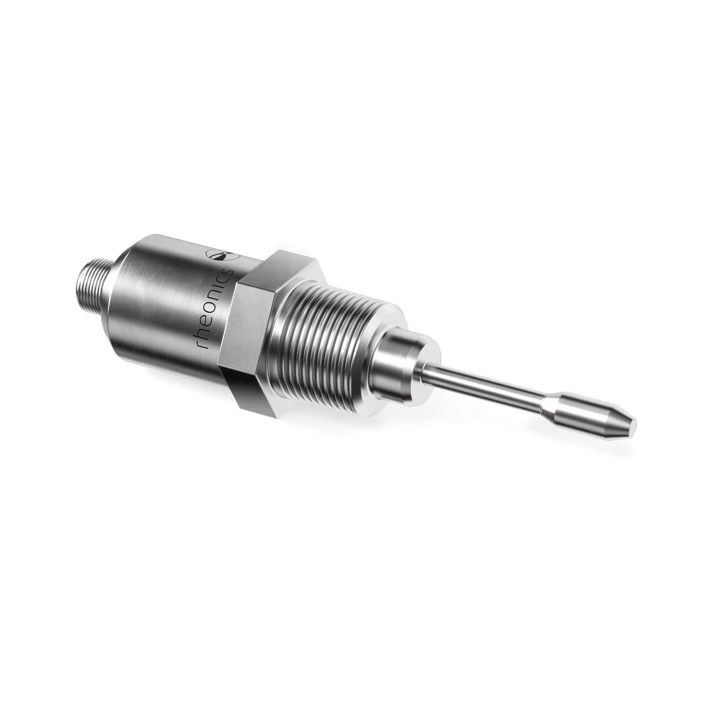
- Compact form-factor for simple installation
- Real-time, stable, repeatable and reproducible measurements in Newtonian & non-Newtonian fluids
- Track viscosity change over wide range with one sensor
- Insensitive to mounting conditions and ambient noise
- Built in fluid temperature measurement
- Operational to 7500 psi (500 bar) and 575°F (300°C)
- Easy to clean, zero maintenance, no re-calibration ever!
Inline Process Density Meters Comparison
| Torsional Balanced Resonator Density (Rheonics DVP) | Tuning Fork Density | Coriolis Flow Meter: Density | Vibrating tubes | |
|---|---|---|---|---|
| Density Range | 0 – 3 g/cc | 0 – 3 g/cc | 0 – 3 g/cc | 0 – 3 g/cc |
| Density Accuracy | 0.001 g/cc (0.0001 g/cc and better demonstrated) | 0.001 g/cc (0.0001 g/cc for defined conditions) | 0.001 g/cc (0.0001 g/cc for defined conditions) | 0.001 g/cc (0.0001 g/cc for best conditions) |
| Viscosity rating Viscosity influence | Up to 300 cP Simultaneously measures fluid dynamic viscosity. 0.001 g/cc accuracy throughout. | Up to 50 cP Higher viscosity (up to 200 cP) fluids have a larger error of 0.004 g/cc. | Density measurement should not be affected. Coriolis meter calibration constants change for high viscosity fluid. | Needs to be calibrated for each viscosity fluid. Significant viscosity influence, can not achieve density accuracy without re-cal. |
| Pressure rating Pressure influence | 0 to 15,000 psi (1000 bar) Fully compensated. No need for calibration. | 0 to 3000 psi (200 bar) Significant, not compensated. | 0 to 1400 psi (100 bar), special to 6000 psi (400 bar) Significant, needs to be compensated. | 0 to 750 psi (50 bar) Claimed no influence. |
| Temperature rating Temperature changes | -40 to 200 °C 0.1°C stability. Small mass of sensor. Isothermal conditions enable excellent density accuracy. No difference in factory vs. field conditions. | -50 to 200 °C No inbuilt temperature sensor. Less than 1°C stability. Huge mass of sensor. Needs external temperature measurement. | Standard to 60 °C, HT version to 350 °C 1°C stability. Large mass of sensor. Significant influence on density measurement. At factory conditions, meets specs. Otherwise far worse. | Max. 150 °C 0.1 °C stability. Sensor tube wrapped in insulation and with controlled heaters. Fast changing fluid temperature leads to high errors in measurement. |
| Flow condition Installation requirement Size | Static or flowing. No influence of flow rate. Needs a 1” instrument port for any pipe diameter. Smallest inline process density sensor in market (1” x 2.5”) | Needs well defined flow regime. Needs a large adapter for each pipe diameter. Large (2” x 10”) | Moving flow. Density can be measured while static. Vulnerable to pipe noise and external vibration. Need complex application-specific installation. Huge size - depends on the pipe diameter. | Static or flowing (needs flow rate information for compensation) Not suitable for flow through installation in large pipe diameters. Large (10” x 20”). |
| Price | $ | $ | $ - $$$$ | $$ - $$$ |
| Installation cost | 0 to Low $ | Medium | High, need straight pipe upstream/downstream | Medium |
| Maintenance | Zero | Coating failure and deposits on sensor. | Regular calibration needed | Frequent calibration & maintenance. |
| Lifetime cost to customer | $ | $$$ | $$$$$$ | $$$$$ |
| Weakness | Large solids can get lodged between the sensing element. Lack of integrated electronics. | Huge wall effect, requires special adapters for each flow condition. | Causes pressure drop. Low flow velocity, vortices. Solid content in fluid and entrapped gas. | High pressure drop High flow rate Needs bypass line |
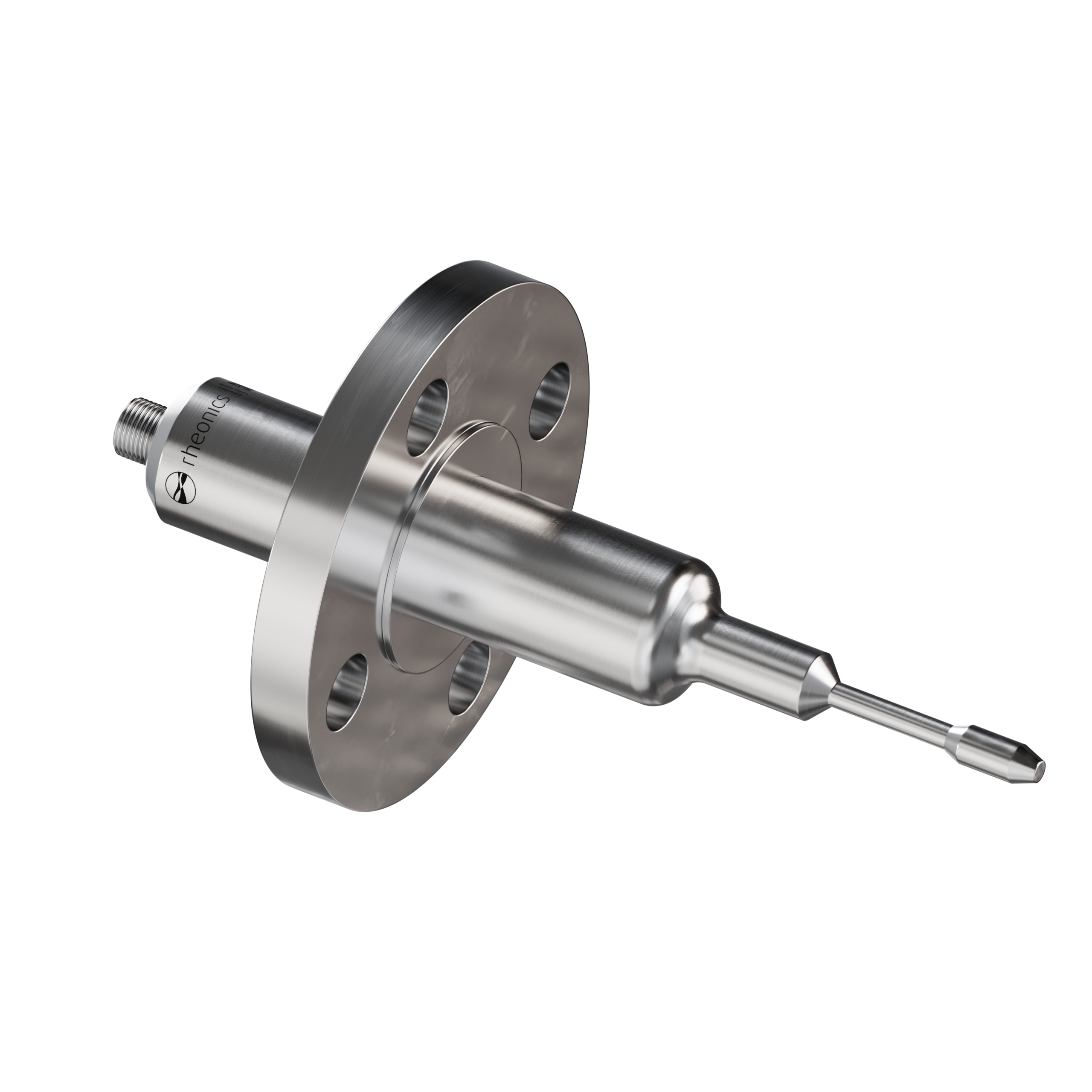
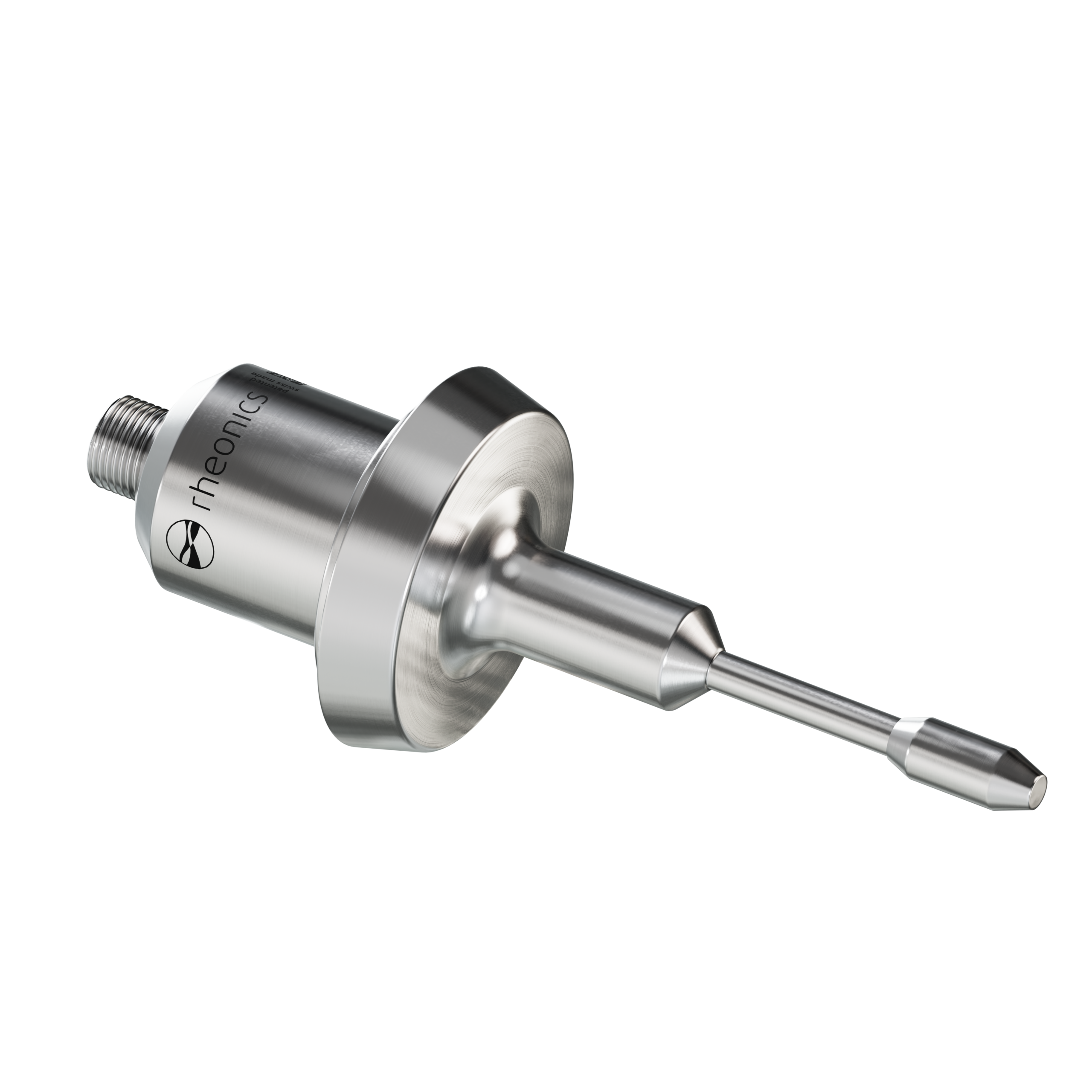
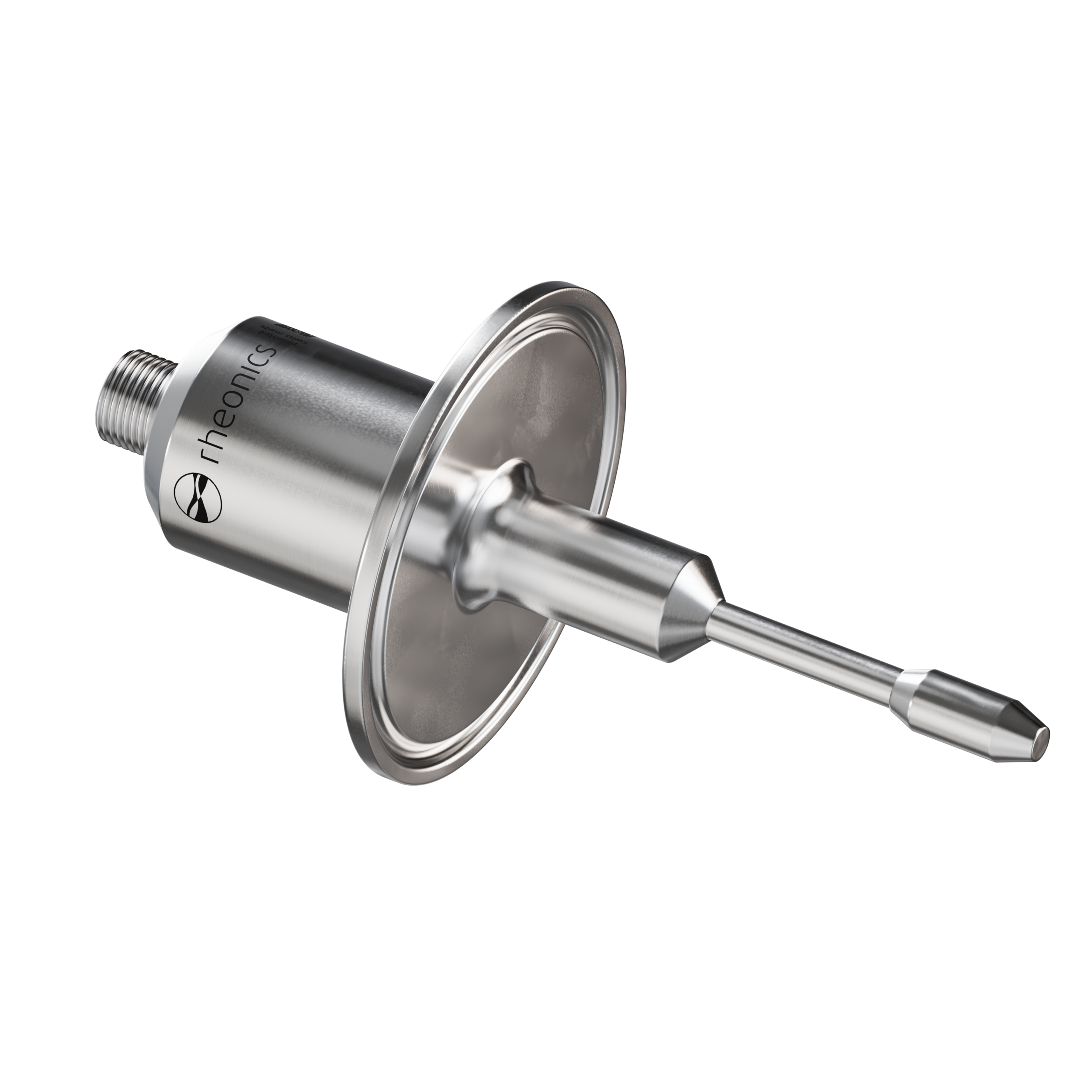
Rheonics Inline process density meters - SRD & DVP
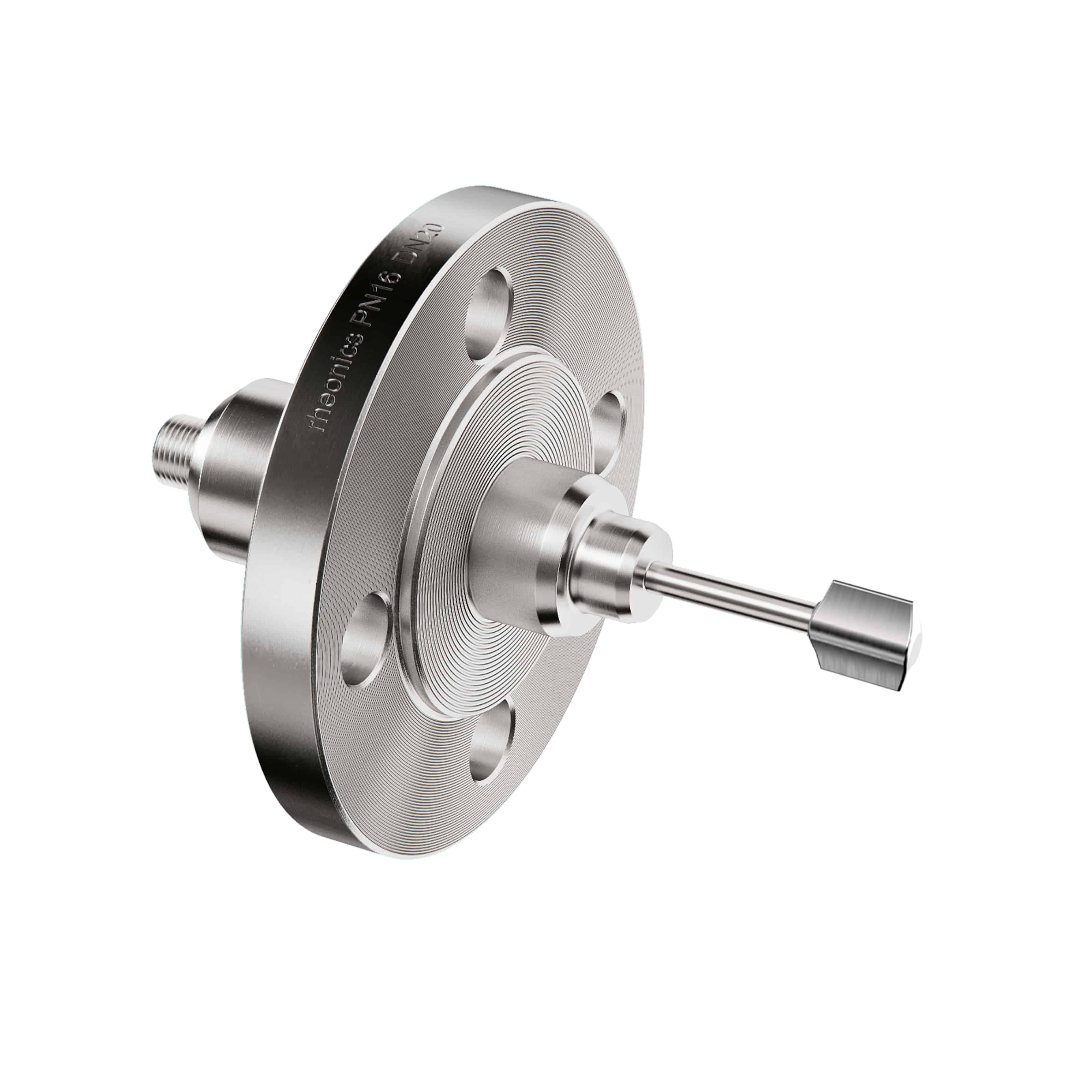
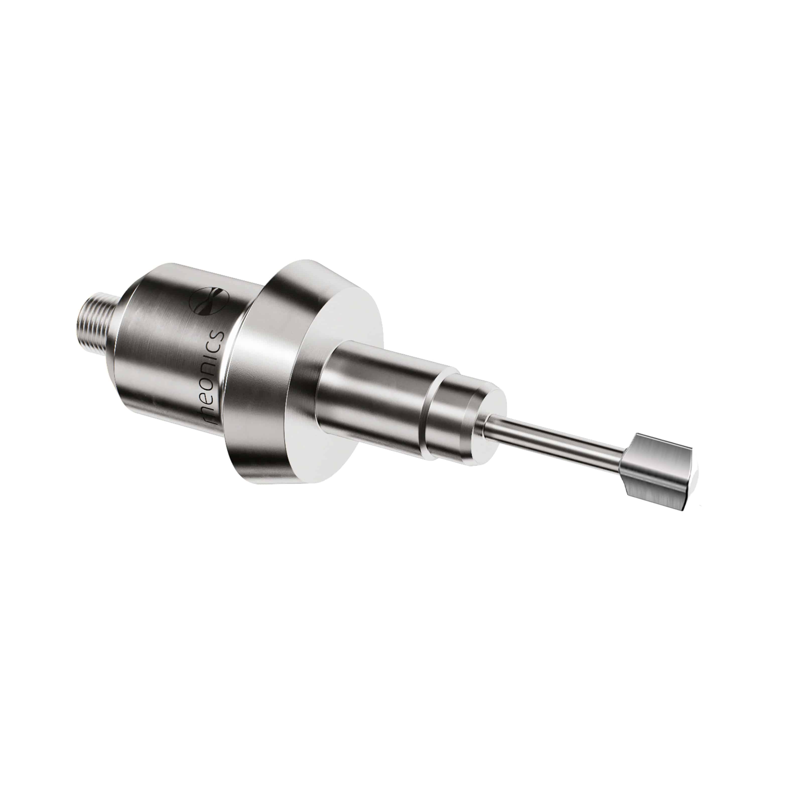
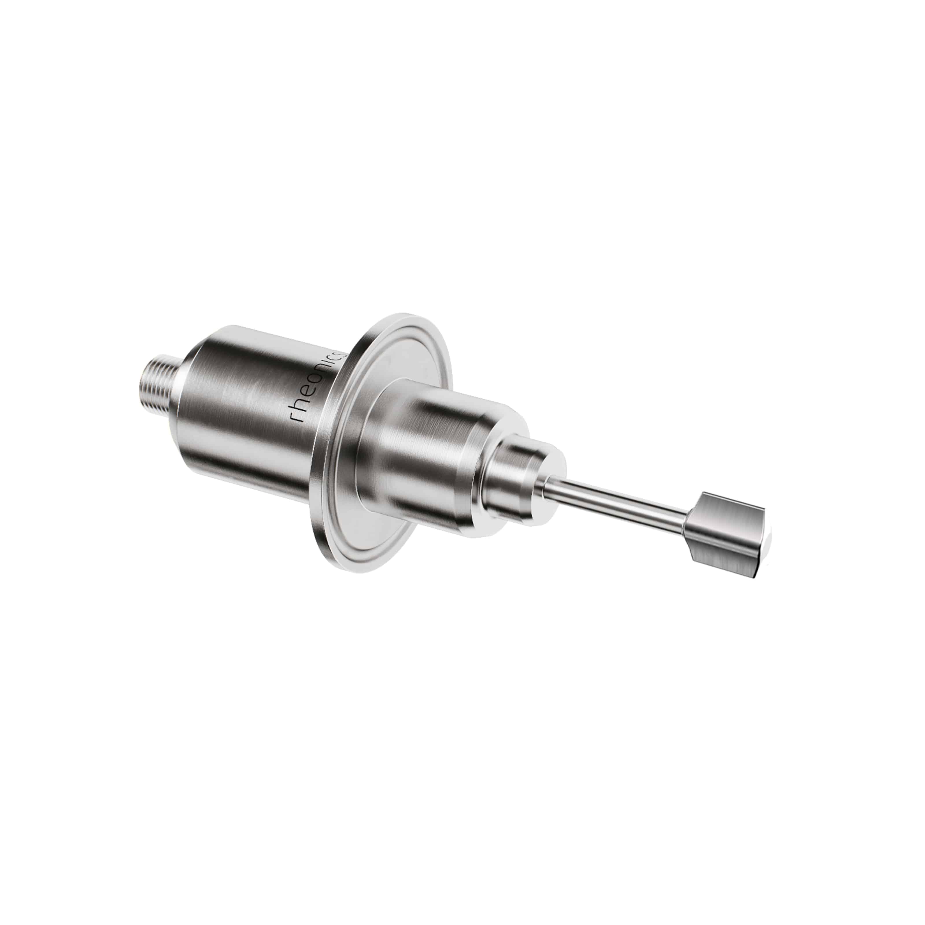
- Single instrument for simultaneous process density (specific gravity), viscosity and temperature measurement
- Compact form-factor for simple installation
- Real-time, stable, repeatable and reproducible measurements in Newtonian & non-Newtonian fluids
- Measures kinematic and dynamic viscosity
- Insensitive to mounting conditions and ambient noise
- Operational to 7500 psi (500 bar) and 575°F (300°C)
- Threaded, flanged and sanitary process fittings
- Easy to clean, zero maintenance, no re-calibration ever!
- Scale across multiple locations/installs without application re-engineering

- Single instrument for simultaneous process density, viscosity and temperature
- Monitor both gas and liquid density and viscosity
- Accurate measurement in the harshest of conditions
- Operational to 10,000 psi (700 bar) & 400 °F (200°C)
- Full Titanium Grade 5 construction
- Rugged – survive and operate even in high vibration and shock
HPHT Density-Viscosity Comparison
| Torsional Balanced Resonator (Rheonics DVM) | Electromagnetic moving piston | Vibrating tube density | Capillary Tubes | |
|---|---|---|---|---|
| Density Range | 0 – 3 g/cc | Cannot measure. | 0 – 3 g/cc | Cannot measure. |
| Density Accuracy | 0.001 g/cc | - | 0.0001 g/cc | - |
| Reproducibility | (0.0001 g/cc and better demonstrated) | - | (0.00001 g/cc for defined conditions) | - |
| Viscosity Range | 0.2 to 300 cP | 0.02 to 10,000 cP (needs 6 pistons) | Cannot measure. Needs to be calibrated to compensate for fluid viscosity. | 0.02 to 10,000 cP with multiple capillaries. |
| Viscosity Accuracy | 1% of actual | 1% of Full Scale | - | Depends on the accuracy of the time keeper. |
| Reproducibility | 0.5% of reading | 0.8% of reading | - | Depends on the accuracy of the time keeper. |
| Pressure rating Pressure influence | 0 to 30,000 psi (2000 bar) Fully compensated, No need for calibration. | 0 to 15,000 psi (1000 bar) Significant, user calibrated. | 0 to 1400 psi (100 bar), special to 6000 psi (400 bar) Significant, needs to be compensated. | Up to 15,000 psi |
| Temperature rating Temperature calibration | -40 to 200 °C Integrated temperature sensor in flow. Small mass of sensor. Isothermal conditions enable excellent accuracy. | Max. 190 °C Huge mass of sensor needs long time to reach isothermal conditions. Needs 40 min or higher for measurement. | Max. 150 °C Large mass of sensor. Significant influence on density measurement. At factory conditions, meets specs. Otherwise far worse. | Max. 200 °C Capillary tubes in oven or bath. Not easy to clean and fill. Needs long time to reach stable thermal conditions. |
| Flow condition Installation requirement Size | Static or flowing. No influence of flow rate. Small size (1.5” x 2” x 1.5”). Easy to integrate in PVT and core flood test setups. | Static or flowing (with adapter & valves). Not possible to integrate in PVT or core flood ovens. Generally used standalone. | Static or flowing. Vulnerable to pump noise and external vibration. Easy to integrate in PVT oven. | Static. Not possible to integrate in PVT oven. Used as a standalone instrument. |
| Price | $$ | $$$ | $$ - $$$ | $ - $$ |
| Installation cost | 0 to Low $ | Medium $$ | Medium $$ | Medium $$ |
| Maintenance | None required. | Needs extensive cleanup. | Regular calibration needed. | Frequent calibration & maintenance. |
| Lifetime cost to customer | $$ | $$$$$ | $$$$$$ | $$$$ |
| Typical measurement issues | Low viscosities below 0.2 cP are measurable but not calibrated currently. | Hard to integrate in a flow loop. Pressure introduces high error. Needs extensive calibration. | Lack of viscosity measurement. Needs recalibration with reference fluid under test pressure with similar viscosity as the sample fluid. | Manual measurements. No flow through. No density measurement. |
HPHT Density-Viscosity - DVM
- Simultaneous density, viscosity and temperature measurement
- Measure at reservoir conditions: 30,000 psi and 400°F (2000 bar and 200° C)
- Built for on the bench or in the field use
- Extremely accurate measurement in the harshest of conditions
- 5 minutes from box to operation in your flow loop – built to integrate with all PVT systems
- Full Titanium Grade 5 construction
Whether you are manufacturing soap or doing PVT analysis on live oil samples, one of our sensor families will fit your needs.