
Introduction
Rheonics sensors are designed to measure real-time viscosity, density, and temperature. They can be installed in a tank or pipe thanks to their versatility, giving process engineers flexibility in how and where they monitor fluid conditions.
The SRV and SRD sensor probes can be ordered with multiple process connection options, allowing them to be mounted in different tank and pipe configurations depending on the application. The sensor probes have a sensing element that needs to be in contact with the fluid of interest during measurements. A small clearance around the sensing element (sensing area) is required to ensure accurate readings.
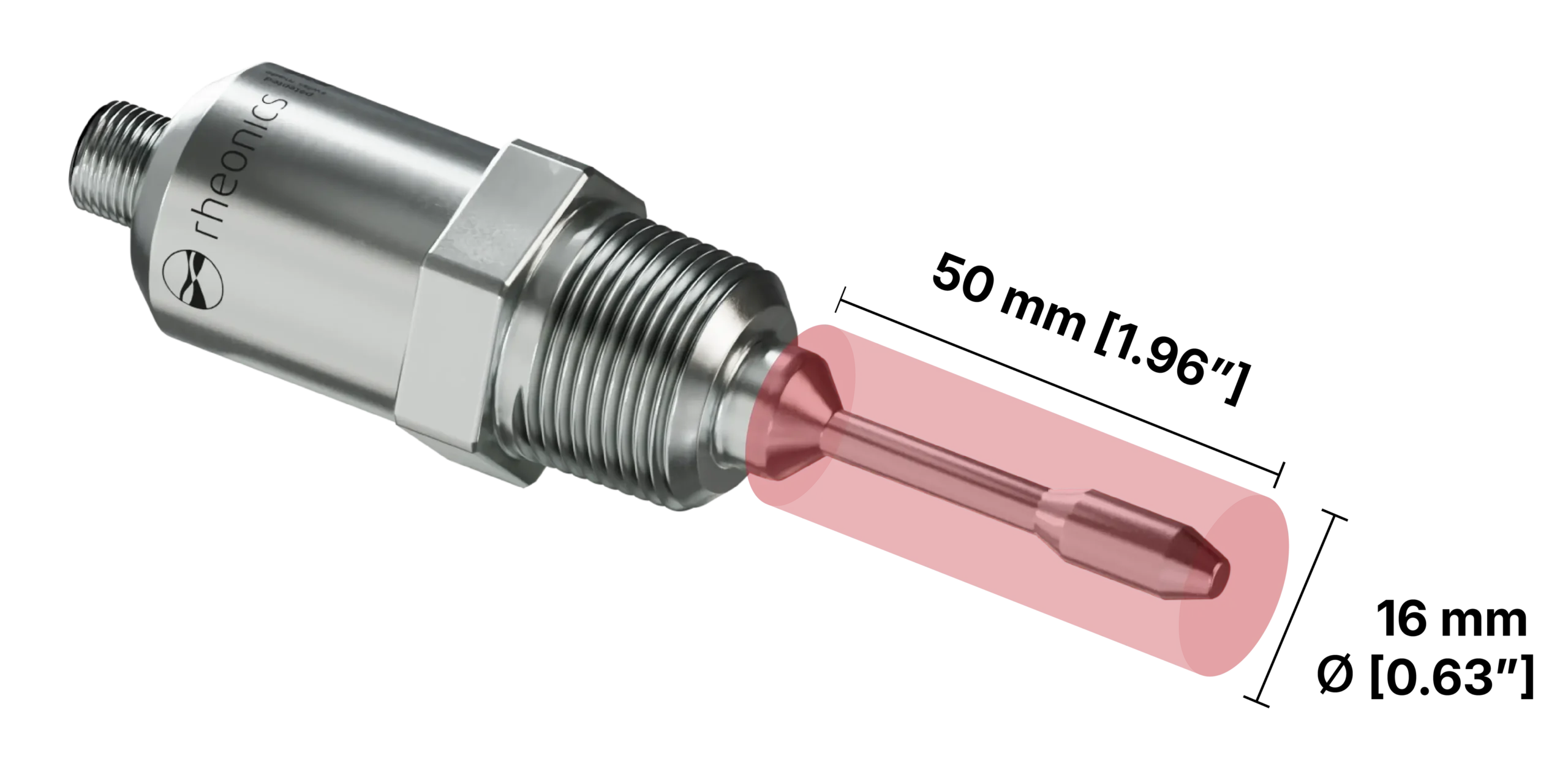
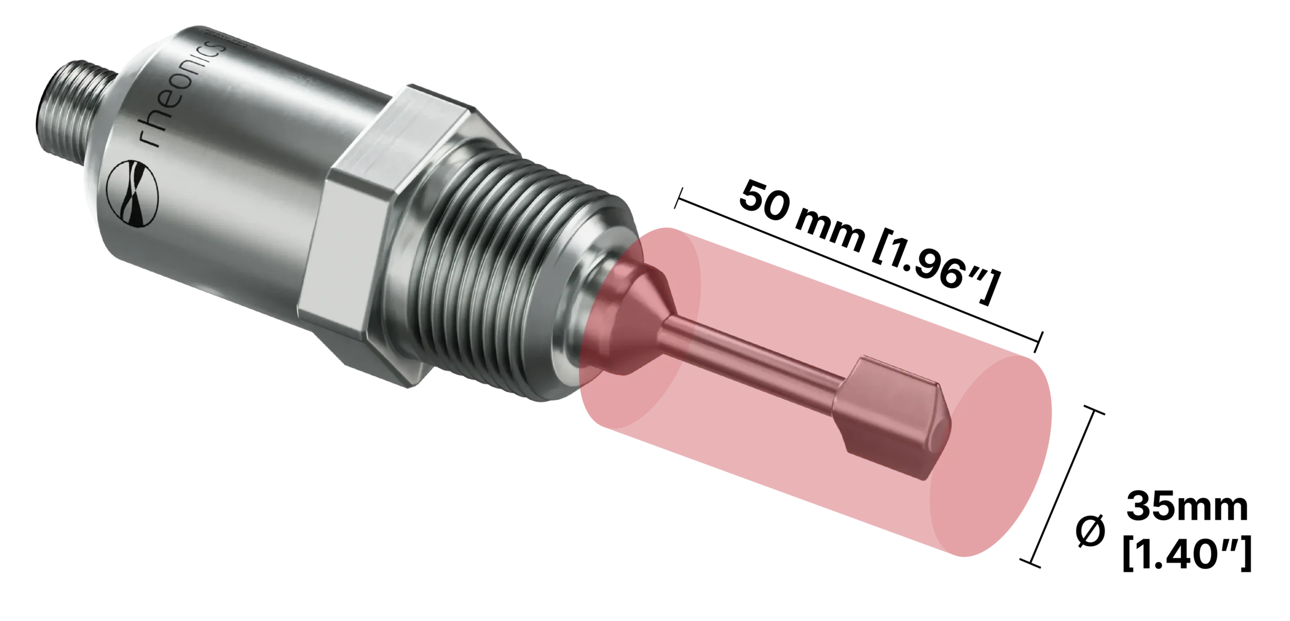
Figure 1. SRV and SRD Sensing Area
In-line measurement in mixing applications can be achieved by mounting the sensor probe on the side wall, bottom, or top of the vessel or tank (See Reference in Figure 2).
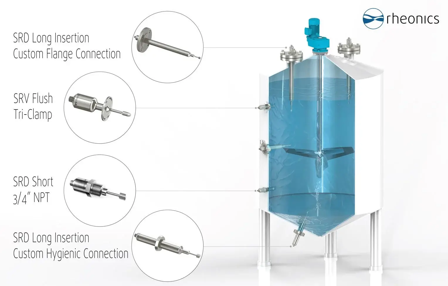
Figure 2. Common installations in a mixing tank
However, in many industrial mixing setups, these conventional installation points are not feasible due to physical constraints such as:
-
Blade geometry that leaves insufficient clearance for a side-wall, bottom-wall, or top-mounted probe
-
Mixing tanks that use scrapers and invalidate a common installation.
-
Vessel design that does not allow direct access to the fluid at the point of interest
In these cases, installing the sensor directly in the mixer shaft provides direct access to the fluid at the most representative location, enabling accurate, real-time viscosity and temperature readings regardless of the vessel geometry.
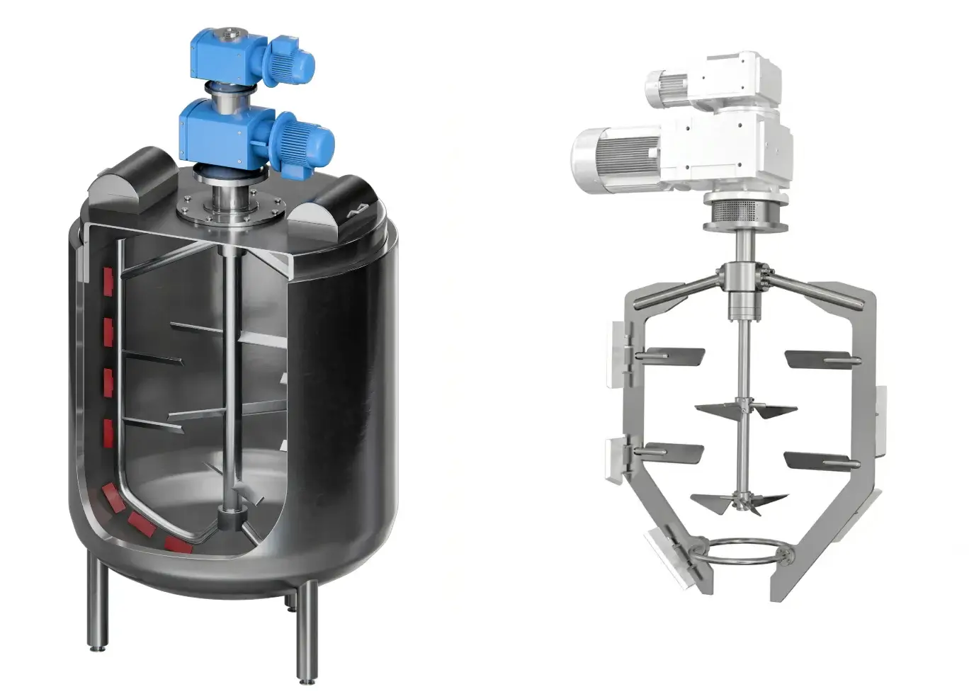
Figure 3. Example of a mixing tank where the common installation is not valid
Solution
Rheonics inline process viscometer and density meter SRV or SRD sensor can be directly mounted onto the mixer shaft, providing a direct measurement regardless of vessel geometry or internal obstructions, delivering real-time viscosity, density, and temperature data from a rotating shaft to a stationary control system. This is achieved using the SRV-EM-TT or SRD-EM-TT sensor variant, a custom-machined thread adapter to mount the probe in the shaft, and a third-party slip ring. The system is described below and illustrated in Figure 4.
As an example, we will use a customer’s case who had an existing M20x1.5 Thread in the shaft with an inside hole of ⌀14 mm for cable connection. However, this can be done with whatever conditions and specifications that other cases have.
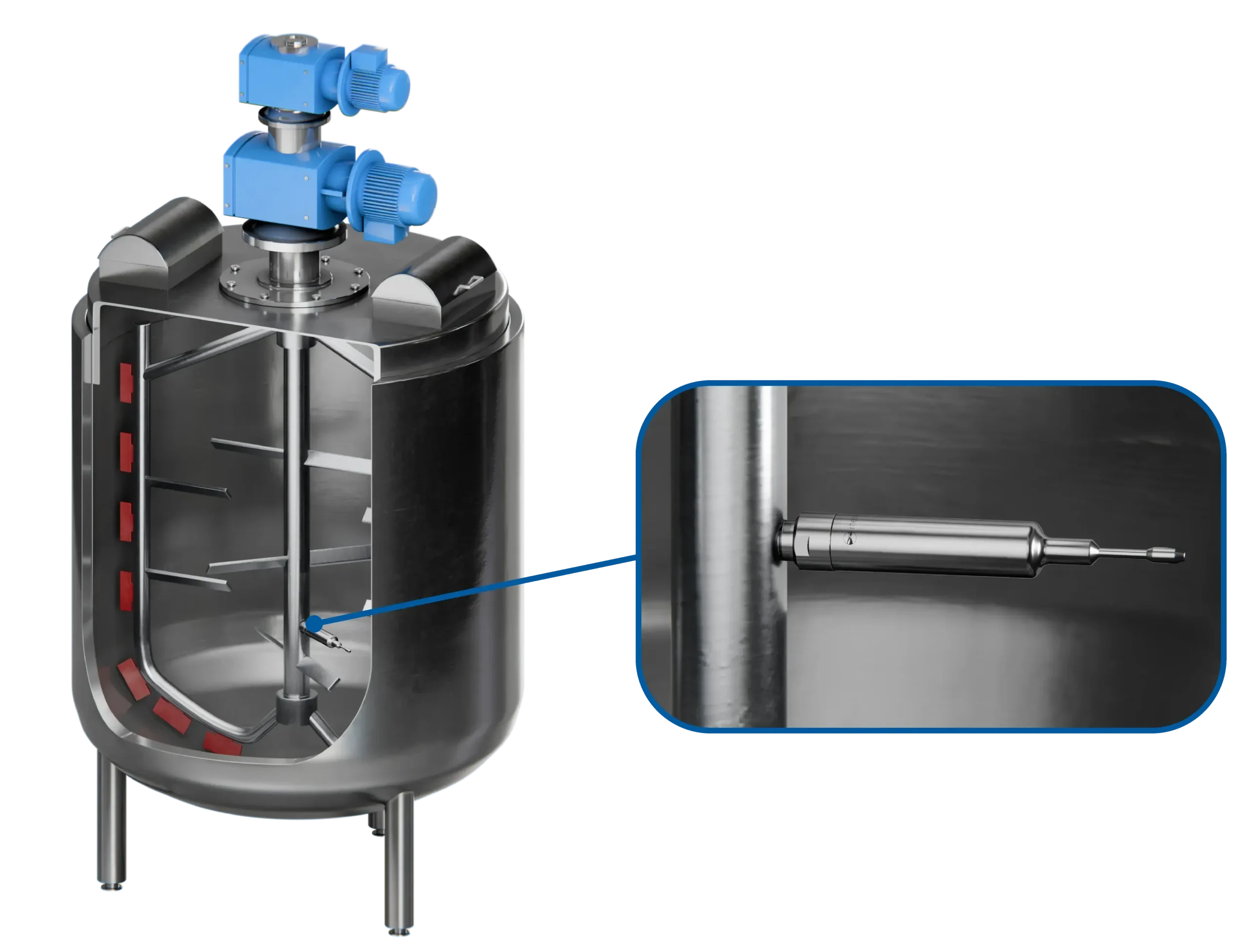
Figure 4. Installation of the Solution Proposed by Rheonics
System Overview
The solution consists of three main components installed in sequence along the mixer shaft and the sensor electronics:
- A custom adapter provided by Rheonics (G3/4″ to M20x1.5) or a third-party workshop to connect the SRV and SRD sensors to the thread on the shaft.
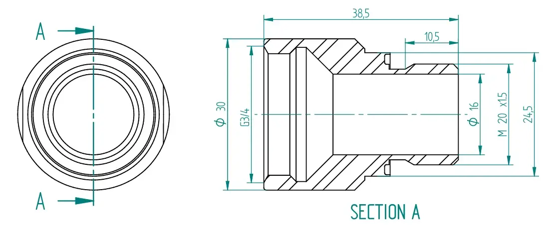
Figure 5. G3/4” to M20x1.5 thread adapter provided by Rheonics
-
The SRV-EM-TT or SRD-EM-TT sensor is threaded into the adapter, with its sensing element exposed to the process fluid. This variant was selected because it integrates the sensor electronics directly into the probe head, eliminating the need for a separate external transmitter.
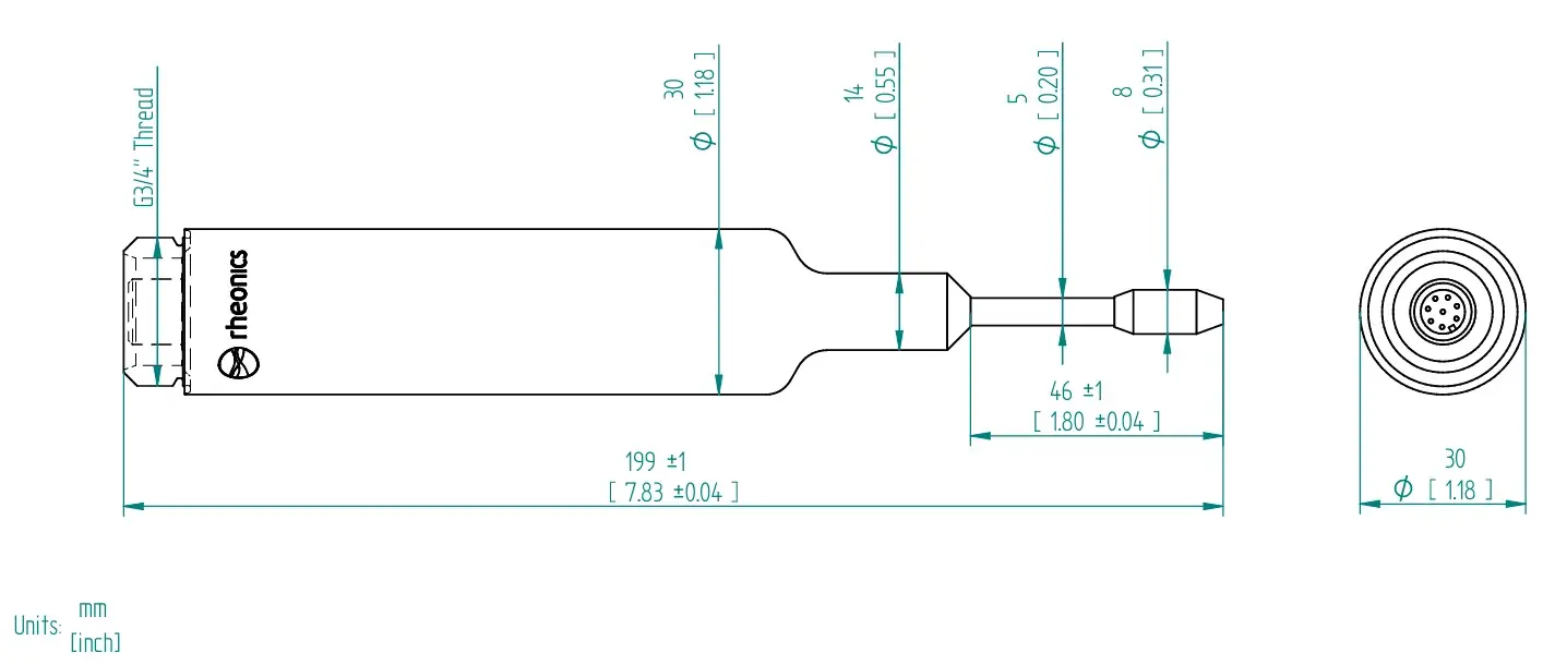
Figure 6. SRV-EM-TT Drawing example
3. A slip ring is installed at the top of the shaft to transfer power and data signals from the rotating shaft to a stationary PC or control system. The slip ring needs 2 conductors for power (8-36V DC) and 2 for CAN connection to the sensor. This piece must be acquired by an external third party like Mercotac or Moflon.
In this particular example, to accommodate the slip ring, the existing shaft bore must be reworked from its current diameter of ⌀14 mm to approximately ⌀30 mm (Depending on the Slip Ring variant), in compliance with the slip ring manufacturer’s installation requirements. This rework has to be performed by the customer or the vessel manufacturer. Rheonics recommends verifying the exact bore requirements against the selected slip ring supplier’s datasheet prior to machining.
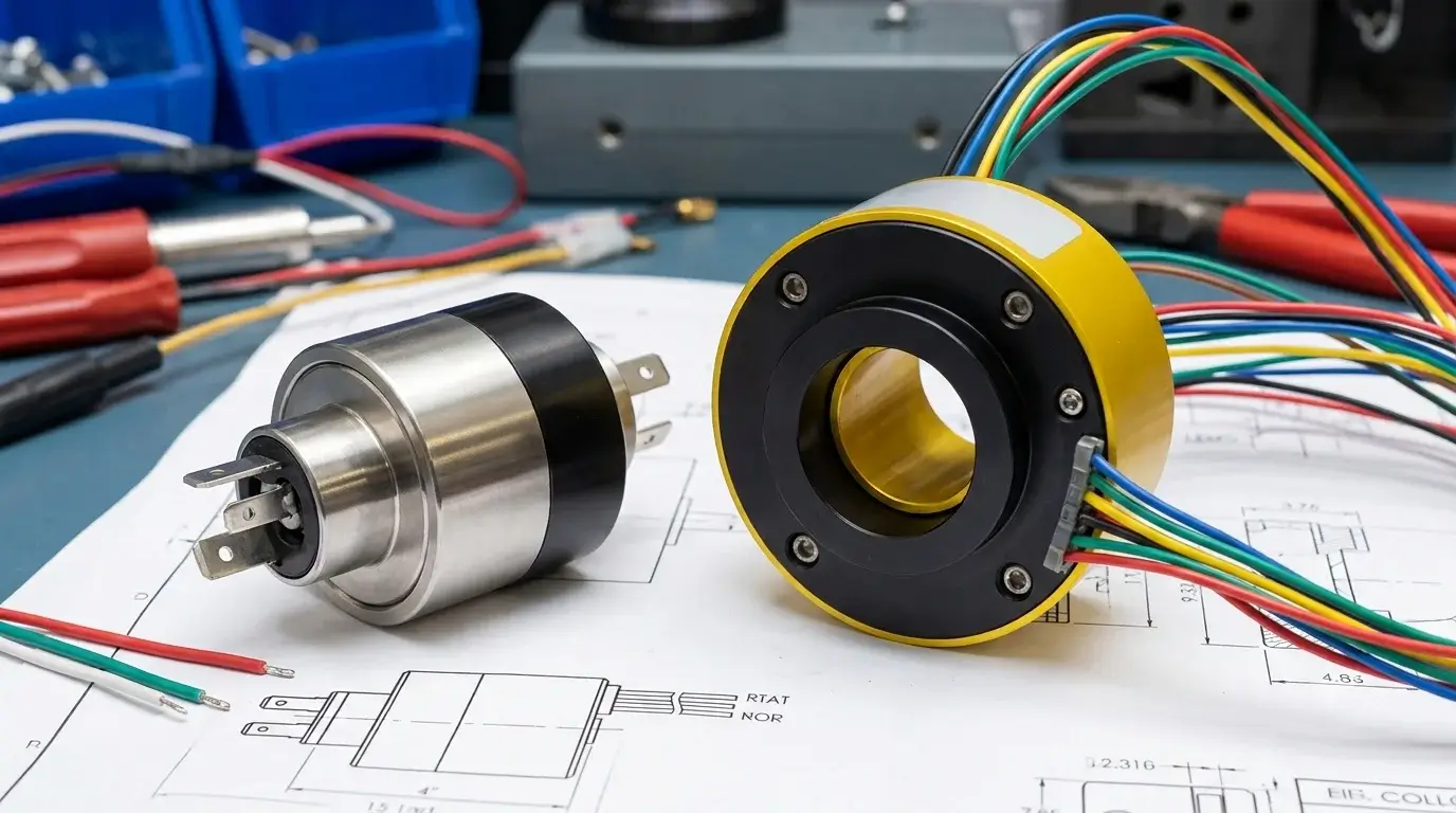
Figure 7. Example of a slip ring provided by the external third-party shop
-
All the Rheonics Sensor electronics variants (E1, E2, and E3) are compatible with this application. The sensor cable connection will be made from the Sensor electronics to the slip ring instead of being connected directly to the Sensor probe. See more about our Electronics variants here.
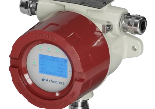
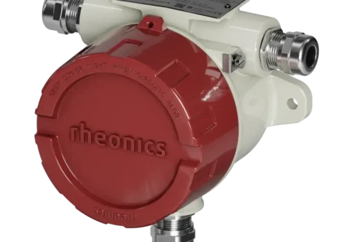
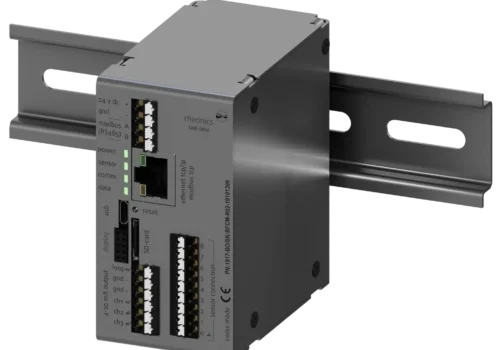
With all the points mentioned before, the final Complete System setup will look as shown below:
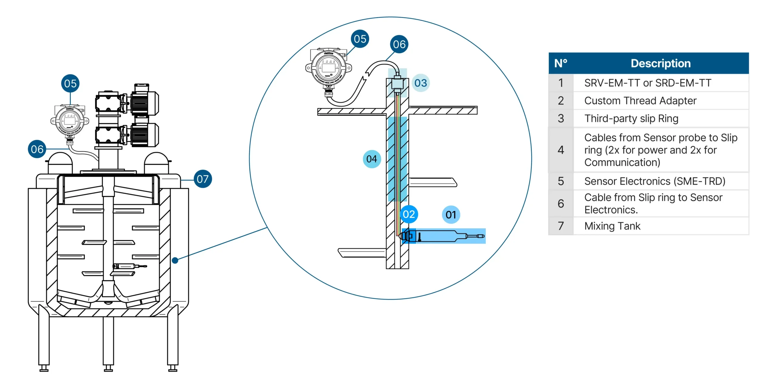
Figure 8. Complete System setup
Forces Analysis
Prior to final installation, it is strongly recommended to perform an internal forces analysis to verify that the hydrodynamic forces generated by the mixing process will not damage the custom adapter or the Sensor probe. The analysis should consider:
-
Fluid drag forces acting on the sensor probe at maximum operating speed
-
Bending moment at the adapter-shaft interface
-
Vibration and fatigue loads over the expected operational lifetime
-
Material compatibility of the adapter with the process fluid
Rheonics can provide sensor mechanical specifications upon request to support the forces analysis.
Verification Steps
After installation, the following verification steps must be performed to confirm the system is operating correctly and that measurement quality is acceptable.
Mechanical Check
-
Confirm that the custom adapter is fully threaded and torqued to specification on both the shaft and the sensor.
-
Confirm that the slip ring is correctly seated and secured according to the manufacturer’s instructions.
-
Rotate the shaft manually and verify there is no mechanical interference with surrounding components.
-
Inspect the adapter-shaft interface for any signs of stress, deformation, or misalignment.
Electrical Check
-
With the shaft stationary, verify that the Sensor powers on correctly through the slip ring.
-
Check continuity of all signal lines through the slip ring contacts.
-
Verify that the sensor is detected and communicating with the connected PC or control system.
Noise Level Assessment
Mixing-induced mechanical vibration and electrical noise from the slip ring contacts can affect measurement quality. Perform the following checks:
-
With the mixer running at operating speed but without process fluid (dry run), observe the raw sensor signal output. Record baseline noise level.
-
Fill the vessel with the process fluid and run the mixer at low speed. Observe viscosity and temperature readings for stability.
-
Gradually increase to operating speed. Monitor for any step changes, spikes, or increased noise in the measurement output that correlate with RPM.
-
If elevated noise is observed, check the slip ring contact condition and cable routing. Ensure signal cables are shielded and properly grounded.
-
Acceptable noise threshold: readings variation should not exceed the sensor specification under normal operating conditions. Contact Rheonics support if noise levels are outside the expected range.
Note
The SRV-EM-TT and SRD-EM-TT sensors are designed with Rheonics patented BTR (Balanced Torsional Resonator) technology, which provides inherent immunity to external vibrations. However, direct mechanical contact with the rotating shaft may introduce additional noise that must be evaluated on a case-by-case basis.
Disclaimer: This is a reference design and not available for ordering from Rheonics. It is documented here to provide design guidance for OEMs. Designers should verify the suitability of the components they select for their application. Third-party parts shown here are only representations of typical parts that can be used. No endorsement or warranty of these parts is implied, and Rheonics assumes no liability for their integration or performance. If you are a mixing vessel manufacturer and would like to integrate the Rheonics sensors in your shaft, please contact