Viscosity Management in Medical Device Coatings: Enhancing Performance and Compliance
Viscosity and density play a crucial role in medical device coatings, directly impacting product cohesion,…
Coil coating is a high-speed, precision process where fluid properties directly affect coating uniformity and adhesion. Inline viscosity and density monitoring allows operators to detect deviations instantly, ensuring consistent quality, reducing scrap, and optimizing throughput.
Table of Content
![Figure 1 - Color-Coated coils [1]](https://rheonics.com/wp-content/uploads/2026/01/color-coated-coils.jpg)
Coil coating is a continuous process where metal strips are coated with primers, paints, or protective layers for construction, appliance, and automotive applications. The process requires precise control of coating fluid properties to achieve uniform thickness, proper adhesion, and surface finish. Viscosity and density are critical parameters, as they influence coating flow, leveling, wetting, and curing.
Traditional lab-based sampling measurement methods, such as Zahn cups or rotational viscometers, can be slow and may not represent process conditions accurately. Inline measurements provide real-time data, enabling immediate adjustments to maintain consistent quality and reduce scrap.
Rheonics sensors provide operational advantages:
Coil coating processes require precise control of coating formulation properties to ensure uniform film thickness, surface finish, and curing performance. Inline monitoring of rheological properties such as viscosity and density is critical for maintaining coating stability during application, circulation, and recirculation.
![Figure 2 - Coating stage with liquid paints [2]](https://rheonics.com/wp-content/uploads/2026/01/coating-stage-liquid-paints.jpg)
Coil coating materials typically include primers, basecoats, and topcoats, which can range from low- to high-viscosity formulations:
Continuous inline measurement supports consistent coating quality across different colors, materials, formulations, and production speeds. Coatings are applied using a roller. Lines operate at high speeds (up to 1000 m/min), making real-time control of coating fluids critical.
Inline viscosity and density monitoring help operators prevent defects, maintain proper coating weight, and ensure consistent pigment distribution.
Viscosity measures a fluid’s resistance to flow. In coating processes, viscosity affects:
Density measures the mass per unit volume. In coating lines, density affects:
Inline real-time monitoring solves challenges associated with lab-based measurements, such as non-representative sampling, time delays, and difficulty replicating process conditions.
A coil coating line is designed to run at a constant speed throughout all its stages. This is achieved by using accumulators at the beginning and at the end of the line.
The process begins with an uncoiler and a welding section to join new material. It then moves through an entry accumulator, which ensures continuous production during coil changes. Next, the uncoiled strip passes through a cleaning section to remove any contamination from the metal surface.
At this point, the sheet enters the coating stage, where it first passes through the first roller coater to apply a primer coating. The applied coating is then cured and dried. Afterwards, the sheet receives a topcoat material in the second roller coater, followed by another curing and drying step before the next stages.
At this stage of the process, viscosity and density sensors can be installed to monitor the coating fluids at different locations, like supply tanks, recirculation lines, hoses with inline flow cells, or coating trays, as shown in Figure 4.
Finally, the coated strip passes through the exit accumulator and recoiler, where it is cut at the coil’s end and prepared for the next batch.
Rheonics Type-SR sensors (SRV and SRD) measure viscosity, density, and temperature inline for process monitoring and control. The SRV measures viscosity and temperature, while the SRD also provides density.
These sensors are factory-calibrated and require no recalibration during their lifetime. However, clients may need calibration or verification for quality control. Optional adjustments or offset corrections can match specific references. For details, see Calibration of inline process viscometer SRV in field and factory.
Rheonics sensors use balanced torsional resonator (BTR) technology. This patented design makes the sensors compact, lightweight, and resistant to external vibrations.
Rheonics SRV and SRD sensors are well-suited for coil coating lines. Installed directly in the coating circulation or supply lines, they provide continuous real-time measurements of coating properties during production. Inline readings enable consistent coating quality, reduced solvent and material waste, and improved line stability across color and formulation changes.
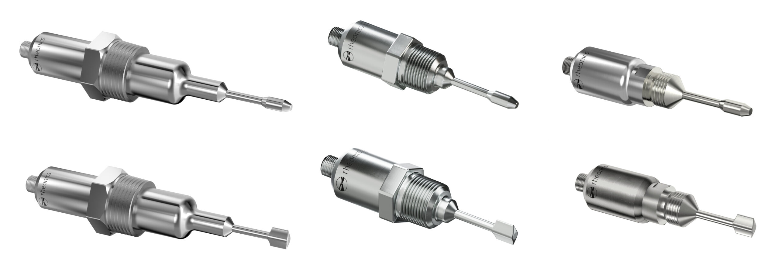
Certain installation aspects apply to both Rheonics sensors, SRV and SRD. Each probe type shares the same resonator design across variants. Proper installation requires correctly positioning the probes’ sensing area (red-shadowed areas in Figure 6) on site:
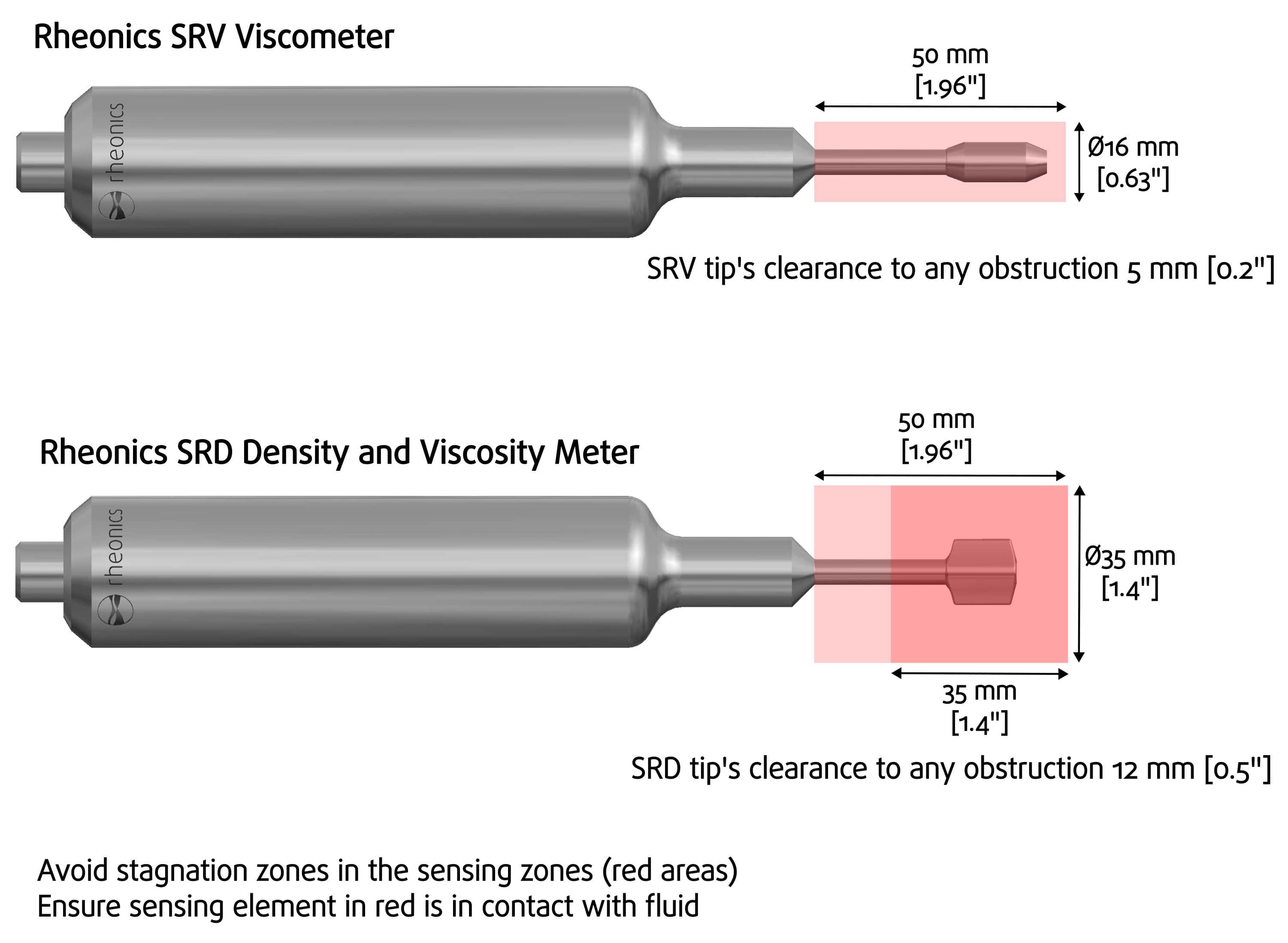
Getting representative measurements of your fluid is simple; ensure that:
In addition to the two main requirements above, the SRD sensor has two additional considerations:
These conditions can be reviewed in more detail in the next article, SRV and SRD Suitable Installations.
The Rheonics Type-SR sensors feature a modular, compact design that supports various configurations depending on application conditions. For example:
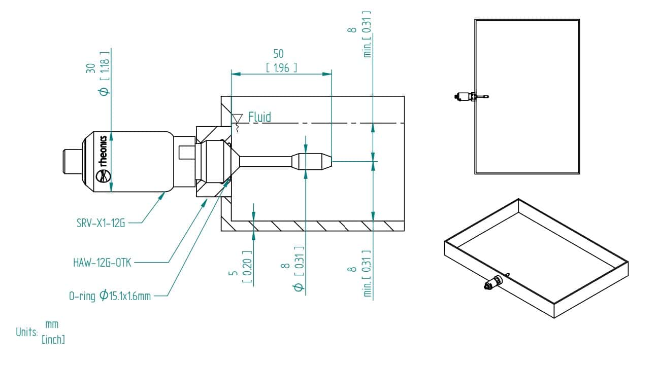
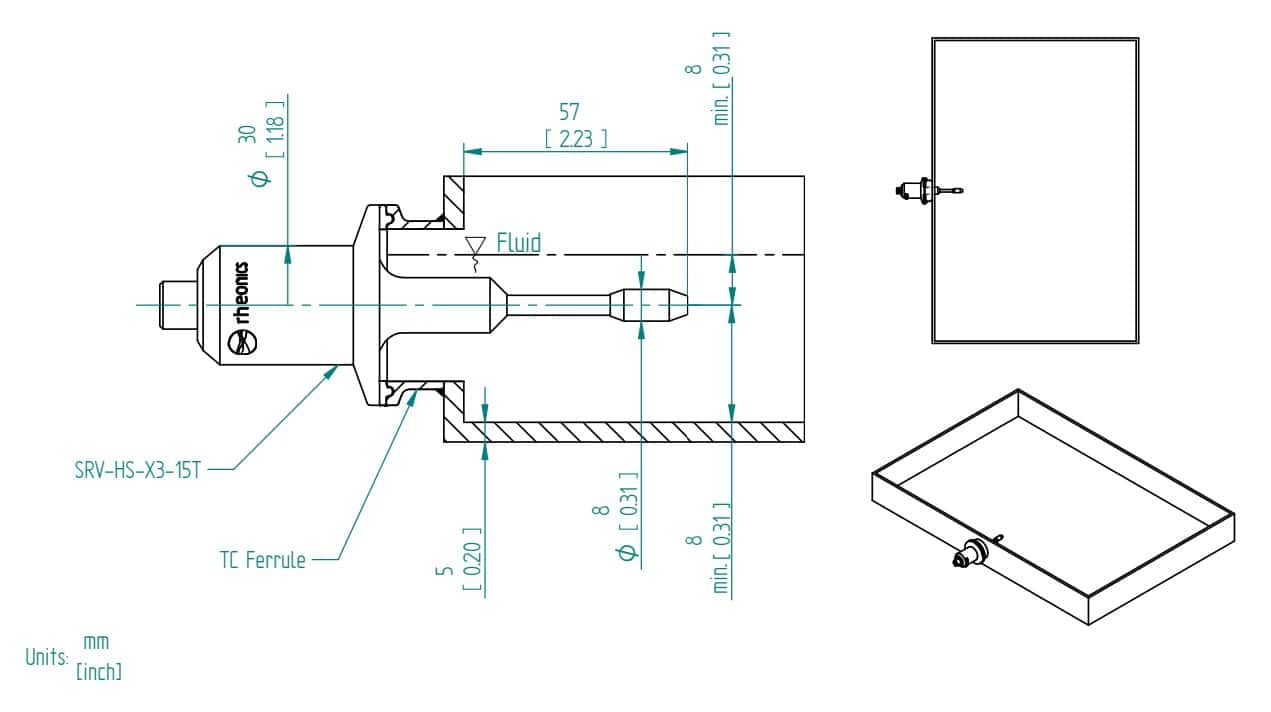
Installation in trays or dishes
Coil coating applications usually use trays to hold fluid during the coating process. Rheonics’ Type-SR sensors can be installed directly in the tray using our HAW (MTK or OTK) and WFT weldolets. Below are example drawings of these accessories installed in fluid trays.
HPT-12G: HPHT flow cell
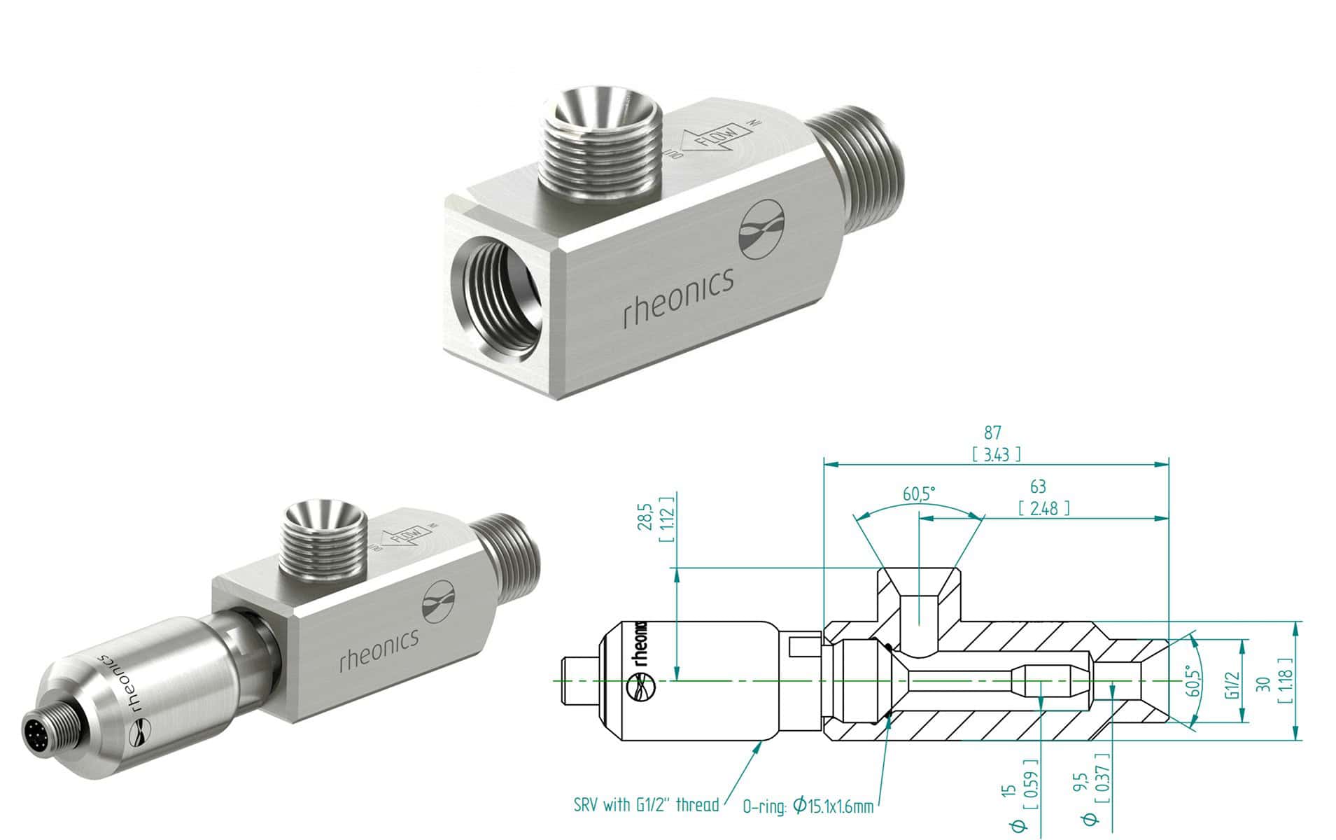
For small pipelines or hose installations, Rheonics offers the HPT-12G (see Figure 10). This flow cell suits high-pressure, high-temperature processes and positions the sensor parallel using a threaded process connection.
The HPT-12G works only with the SRV-X1-12G, which has a G 1/2” threaded connection. This ensures a flushable seal compatible with CIP, ideal for coating and paint lines. See HPT-12G for details.
IFC-34N-SRX: Pipe installation flow cell
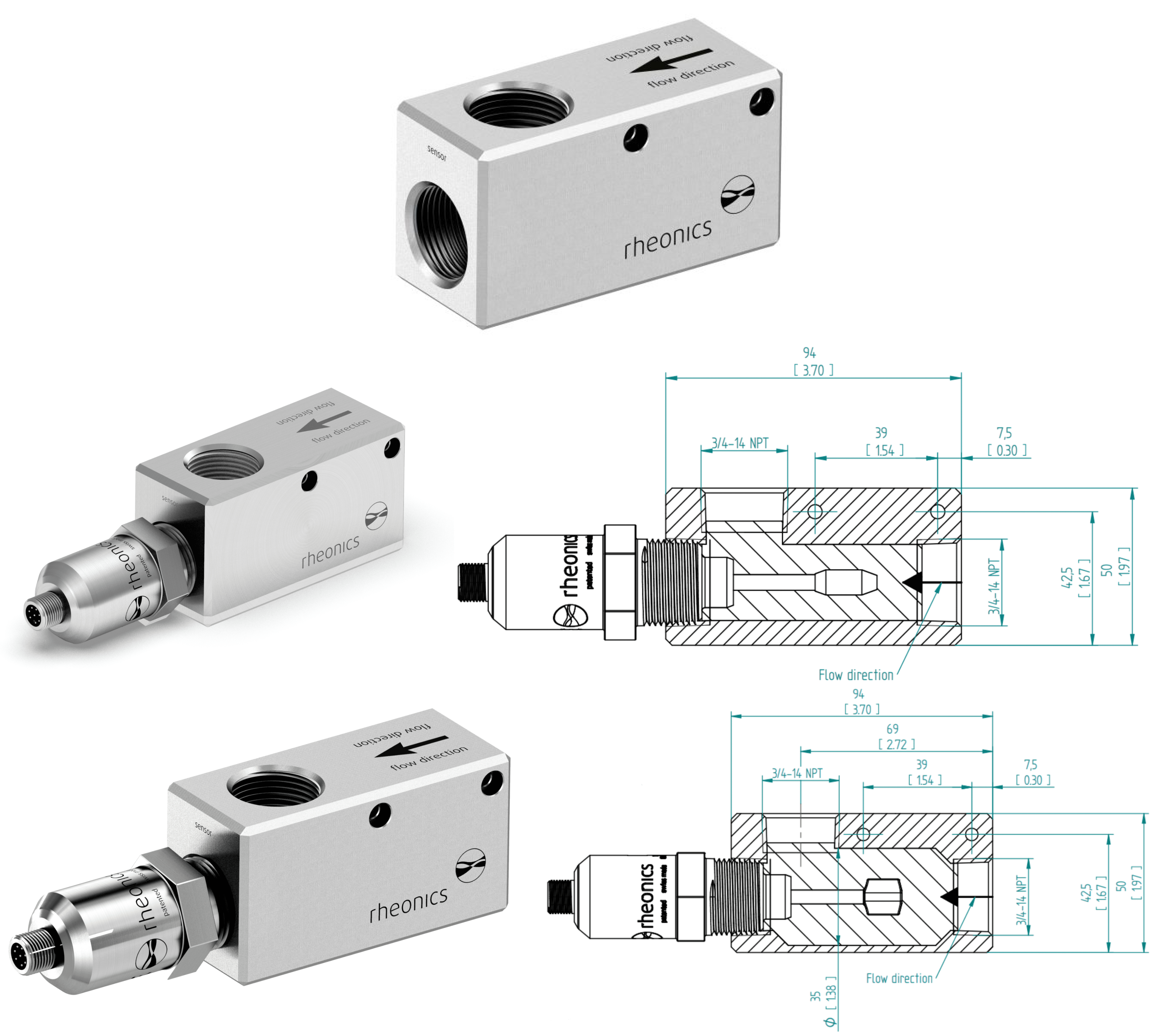
For DN5 to DN25 (1”) pipes inline installation, the IFC-34N-SRD flowcell fits well, positioning the probe paralell with a threaded NPT process connection, as shown in Figure 11.
The accessory works only with the SRV-X1-34N and SRD-X1-34N, both with 3/4” NPT threaded connections. It has inlet and outlet ports of the same size to connect tube adapters or tubes for recirculation or bypass lines. For details, see IFC-34N-SRV and IFC-34N-SRD.
Flow speed limit
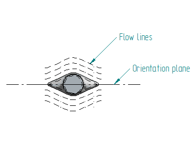
Rheonics sensors are generally compatible with flow speeds up to 10 m/s, since atomizer supply lines, flow speeds can reach such high velocities to prevent settling, it is recommended to install the probe parallel to flow direction in elbows, as this can reduce mechanical impact, however, speeds in this range can still add too much noise to readings. For more details, see Rheonics Type-SR sensors for high flow rate and high viscous applications
Cleaning Process and CIP/SIP Procedures
Periodic cleaning of the SRV or SRD sensor might be necessary to ensure long-term accuracy. Coating fluids tend to form sediment or solid deposits that can adhere to the sensor tip and distort readings, especially in high-viscosity conditions. For more information on cleaning procedures, seeHow to clean your Rheonics probe?.
Additionally, the mechanical design of the sensors is hygienic by default, making the sensors suitable for Clean-in-Place (CIP) procedures.
Moving Parts and Obstructions
Coating solutions and materials are often prepared in mixing tanks with mechanical components such as stirring arms or paddles. It is essential to ensure sufficient clearance between the sensor and any moving parts to avoid interference or damage.
Bubbles
Regarding bubbles, the SRV sensor is not affected by the presence of bubbles in the fluid. In contrast, the SRD sensor, which measures both viscosity and density, is not recommended to be used with high concentrations of bubbles since this may lead to measurement inaccuracies, as the density measurement is more sensitive to these.
Viscosity and density play a crucial role in medical device coatings, directly impacting product cohesion,…
Adhesive hotmelt’s viscosity is a critical property, as it directly impacts its ability to be…
Paint, ink and coating manufacturing processes follow similar steps, from initial mixing, until final packaging…
Defects in glaze coating are driven by variation in glazing causing color differences, coating thickness…