Enhancing Safety and Process Control in Combustible Dust Environments with EX Certified Rheonics Density Meters and Viscometers
Combustible dust poses a significant explosion risk across industries such as food processing, chemicals, mining,…
Polymer melt viscosity measurement during extrusion process has a paramount relevance for the melt quality, a much bigger relevance than temperature and pressure monitoring.

Figure 1: Extrusion machine.
Table of Content
Extrusion molding is a highly efficient and versatile manufacturing process across various industries used to produce continuous profiles, such as pipes, sheets, films, etc. It allows high production speed, material efficiency, and the ability to create complex cross-sectional shapes with consistent quality. Extrusion manufacturing plays a major role in the global polymer and plastics production. In recent years, advancements in automation, real-time process monitoring, and sustainable materials, as well as the relevance of recycling processes, have enhanced precision and reduced environmental impact by reducing waste.
Real-time process monitoring is key to ensuring high-quality products. Great advances have been achieved in temperature and pressure monitoring of extrusion processes. However, inline viscosity monitoring, despite being one of the critical factors affecting melt flow and die fill, even more significant than temperature and pressure, has faced multiple challenges. Different methods have been tested for viscosity measurement with better or worse results related to the cost, calibration, repeatability, etc., that affect the confidence of the operator. Under these circumstances, Rheonics SRV inline viscometer enables repeatable viscosity measurements in the harsh conditions of extrusion machines, thus filling the gap for complete polymer extrusion process control.
Extrusion can be defined as a continuous manufacturing process used to create objects (an extrudate) with a consistent cross-section by forcing a molten material through a die or orifice to form a shape. An extruder can also be used as a part of other manufacturing processes (thermoforming, injection, blow molding, etc.). Extrusion is widely used in the plastic, metal, and rubber industries to produce products like pipes, tubing, sheets, films, and profiles.
The main focus of this case study is polymer extrusion. In contrast with metal extrusion, polymer extrusion can be done continuously as long as the material is fed to the extrusion machine. Extrusion is used mostly for Thermoplastics, but Elastomers and Thermosets can also be processed.
An extrusion machine generally consists of the following parts. A hopper, where the polymer material is fed into. A feeding screw is in constant rotation along a barrel. The screw is powered by a motor drive unit and gearbox and forces the material to flow through a die. Heating elements, located over the barrel at a controlled temperature, soften and melt the polymer material. After the die, a mold with one or multiple cavities can be used, where the melt material is cooled down to take the shape of a desired object. Some machines use a gear pump between the end of the barrel and the die to maintain a well-defined constant pressure in the outgoing material.
The ability of the screw and barrel assembly to extrude a given material is dependent on the characteristics of the plastics material, the characteristics, or construction, of the screw and barrel, and the conditions under which the system is operated.
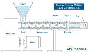
Figure 2: Polymer Extrusion Machine Main Parts.
Polymer extrusion is a complex process that requires precise control of multiple parameters to ensure high-quality output. Despite advancements in technology, several challenges persist in both the extrusion process and its control systems. These challenges can impact product consistency, efficiency, and overall manufacturing costs.
Key process parameters are screw rotational speed, die and barrel temperatures, melt viscosity, melt temperature, mass flow rate, melt pressure, cooling rate, etc. [1]. Temperature and pressure are considered the most common in-line monitored parameters in the extrusion process thanks to multiple technologies available. However, melt viscosity (described as the resistance of fluid to flow) is not easy to measure or monitor in line despite being one of the most crucial parameters in the process. Viscosity of the melt relates to multiple characteristics, such as:
High viscosity of the melted fluid can cause poor flow, excessive pressure, and die clogging, leading to defects like surface roughness and warping. In contrast, low viscosity can result in sagging, excessive shrinkage, or weak mechanical properties. Then, the goal will be to maintain the viscosity as constant as possible over the extrusion process.
In most cases, plastics are pseudo-plastic materials, which means that they become less viscous (easier to flow) when they are moved (sheared) faster. Therefore, there is not a linear relationship between pressure and flow, nor between shear stress (force per unit area, measured mostly in Pa) and shear rate (rate of motion of fluid’s parallel layers, measured in s-1).
Currently, there is no suitable inline sensor for monitoring viscosity in real time in extrusion melts. Capillary Rheometers are well-known laboratory instruments used to study the rheological properties of polymers. It uses a piston to force the melt through a capillary (very fine) die, which tries to simulate the process that happens in the extrusion machine. Despite this being a well-accepted testing instrument for viscosity, it fails to give real-time in-line data of the melt fluid. The main issues of this method are:
SRV is Rheonics Inline Viscometer suitable for wide ranges of viscosity, temperature, and pressure. Rheonics SRV uses a very compact probe with simple installation instructions and no maintenance or recalibration requirements. Due to the SRV compact design, there is a versatility in the installation types that the users take, such as those shown in Figure 3 and 4.
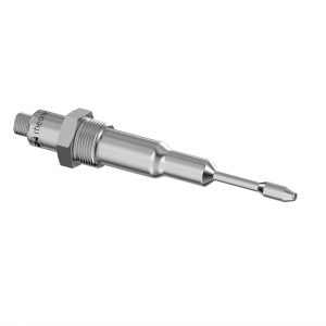
Figure 3: Rheonics Inline SRV Viscometer slimline with threaded connection.
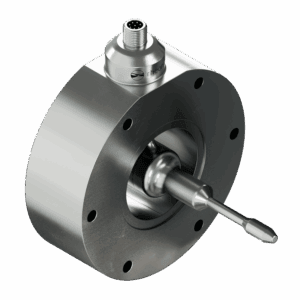
Figure 4: Rheonics Inline SRV Viscometer Stargate wafer-cell design.
Rheonics SRV enables real-time online visualization of key parameters as dynamic viscosity and temperature in extrusion machines. The sensor is easily integrated to local monitoring and control systems through a powerful electronics that runs multiple industrial protocols. Find more information in the Electronics Rheonics Page.
Rheonics sensors also store measurement and sensor status data in an onboard historian. This automatic logger is accessible through the Rheonics RCP Software and is useful for an historical view of the monitored parameters.
Perpendicular Installation
Rheonics SRV is located perpendicular to the melt flow with sufficient immersion to have the sensing element of the probe in contact with the fluid.
The main advantage of this installation is that is likely the easiest of all for installation. The SRV can be installed in existing ports used by temperature or pressure sensors, with the main difference that the SRV probe needs to stick out in the line, this being an intrusive and invasive probe.
This perpendicular installation, however, has the main drawback of exposing the probe to a large bending force due to the fluid’s high viscosity and velocity. Viscous loading can be an issue for the standard SRV probe in perpendicular installation, by adding too much noise or damaging the probe. For relations between line size and mass or volume rate limitations see section “Probe limits in perpendicular installation“ or the article SR probes for highly viscous fluids and high fluid speeds.
The main considerations for this installation are the line size, fluid velocity or flow rate and viscosity ranges. Line size should be bigger than 50 – 55 mm (2”) so that the SRV probe sensing element can be correctly exposed to the fluid. The fluid velocity and viscosity ranges are compared against the table in section “Probe limits in perpendicular installation“ to verify the forces that the probe will be exposed to. Rheonics offers the SRV-HP for cases for High Pressure and high bending forces.
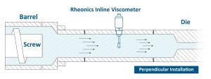
Figure 5: Rheonics SRV perpendicular installation in Extrusion line.
Parallel Installation inserted in elbow
Some extrusion machines have an elbow right before the die to accommodate measurement instruments, like temperature sensors, axially to the flow. This can also be used for Rheonics Inline Viscometer SRV for a parallel installation.
Here the main advantage is the reduction of the force exerted on the probe by the fluid, compared to a perpendicular installation. A parallel installation also keeps the sensing element centered in the line, avoiding deposits that can affect the readings. The SRV-X6 Slimline probe can be used for minimum pressure drop and is compatible with lines smaller than 50-55 mm (2”).
The main limitation of this installation, is the use of an elbow before the die. This requires a lot of intervention to the machine and changes the orientation of the extruded material, rendering this installation option only suitable for extruder machines that have an elbow already in the line. Furthermore, this installation may suffer from fouling or stagnation of fluid around the base of the sensor on the elbow wall. This doesn’t affect the readings but is not desired in any line.
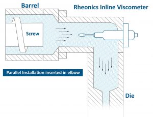
Figure 6: Rheonics SRV parallel installation in elbow in Extrusion line.
Parallel Inserted Inline – Wafer cell process adaption – SRV Stargate
Rheonics Stargate-SRV-EM, also called Stargate Variant, is designed to place the SRV probe suspended in the center of the line installed inline in the process pipes, as in a wafer cell adapter. The advantages of this solution is its resistance against high viscosity and high speed fluids, and the reduction of chances of deposits.
For this installation, an extension section in the line is generally needed and this intervention may not be possible for some clients due to costs, rework or thermal management issues.
Notice that the back side of the probe faces the fluid, this is needed to sustain high forces. Additionally, the SRV Stargate variant needs to be ordered in the same size as the extrusion line, unless reduction and expansion adapters can be used in line.
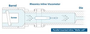
Figure 7: Rheonics SRV parallel “wafer cell” installation in Extrusion line.
Sensing area in contact with fluid
Rheonics Inline Viscometer SRV main installation requirement is to have the sensing area immersed in the fluid without deposits or fluid accumulations, as these can affect the readings. SRV sensing area is shown in Figure 8.
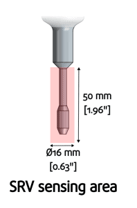
Figure 8: SRV Sensing area.
High Temperature
Extrusion processes normally require a fluid temperature in the range of 180 to 220˚C (360 to 430˚F). This can vary depending on the material, speed, and screw design. Rheonics SRV Inline Viscometer can be configured for temperatures up to 285°C (545 °F). User should select the correct temperature rating during the order. The next Table shows the Temperature ratings for the SRV probe. Some extrusion processes can reach very high temperatures, up to 350/370 °C (670/700 °F), in that case, we suggest you contact Rheonics Support Team at for further information.
Table 1: SRV Inline Viscometer Temperature Ratings
| SRV Temperature Code | Temperature limit |
|---|---|
| T1 | Sensor rated for operation in process fluids up to 125 °C (250 °F) |
| T2 | Sensor rated for operation in process fluids up to 150 °C (300 °F) |
| T3 | Sensor rated for operation in process fluids up to 175 °C (350 °F) |
| T4 | Sensor rated for operation in process fluids above 250 °C (480 °F) |
| T5 | Sensor rated for operation in process fluids above 285 °C (545 °F) |
Note: Sensor cable and sensor electronics have different temperature limits that should not be exceeded.
High Pressure
Extrusion processes can reach very high pressures, up to 10,000 psi, 670 bar, or 70 MPa. Once again, Rheonics SRV should be configured accordingly.
Table 2: SRV Inline Viscometer Pressure Ratings for Extrusion
| SRV Pressure Code | Pressure limit |
|---|---|
| P3 | Sensor rated for process fluids pressure up to 200 bar (3000 psi) |
| P4 | Sensor rated for process fluids pressure up to 350 bar (5000 psi) |
| P5 | Sensor rated for process fluids pressure up to 500 bar (7500 psi) |
| P6 | Sensor rated for process fluids pressure up to 750 bar (10000 psi) SRV-HP |
| P7 | Sensor rated for process fluids pressure up to 1000 bar (15000 psi), SRV-HP |
| P8 | Sensor rated for process fluids pressure up to 1500 bar (20000 psi), SRV-HP |
Probe process connection and sealing
For high-pressure applications, both the probe and process connection must be rated for the expected pressure range. For perpendicular installation Rheonics normally offers G1/2” Thread interface. Whereas for parallel in elbow, a flange or thread connection can be used. The wafer cell installation variant can be integrated through a customer flange interface using an O-Ring or Metal seal. Existing installation ports on the machine can be reused to mount the Rheonics sensor probe.
Contact Rheonics Support Team at for discussion on suitable installation options in your extrusion machines.
Probe limits in perpendicular installation
Under certain conditions, high-viscosity fluids may affect the SRV probe when a perpendicular installation is used. Bending forces caused by the fluid flow can damage the probe (Figure 9). Forces are generally dependent on the fluid’s viscosity and velocity. The next plot shows a relation between a fluid’s velocity in m/s and dynamic viscosity in Pa.s. Clients can use the plot to determine whether the process conditions can damage a standard SRV probe.
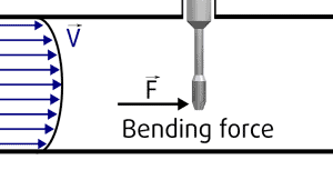
Figure 9: Bending forces on probe due to fluid’s viscosity and velocity.
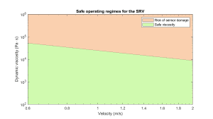
Figure 10: Plot showing fluid velocity on the X-axis and maximum allowed dynamic viscosity on the Y-axis for the SRV.
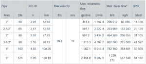
Generally, a limit of 12m/s is recommended for the use of the SRV in perpendicular installations. Going above this limit of velocity may cause too much noise on readings or damage on the probe. The next table shows what this velocity means on volumetric and mass flow for different line sizes.
Learn more about the Type-SR probes to measure highly viscous fluids and high fluid speeds.
https://www.sciencedirect.com/science/article/pii/S2665917422000150
https://www.sciencedirect.com/science/article/pii/S0141391013004497
https://www.dynisco.com/userfiles/files/27429_Legacy_Txt.pdf
H.K. Bruss – Viscosity measurement for the automatic control and monitoring of the uniformity of extrusion processes
Rheonics – SR probes for highly viscous fluids and high fluid speeds.
Combustible dust poses a significant explosion risk across industries such as food processing, chemicals, mining,…
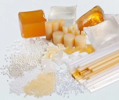
Adhesive hotmelt’s viscosity is a critical property, as it directly impacts its ability to be…
In battery manufacturing, viscosity and density play a critical role in achieving consistent slurry quality,…
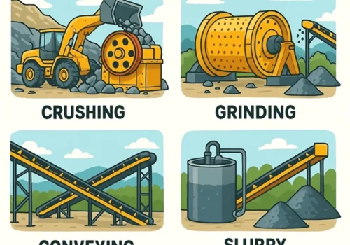
The mining industry has always been known for its complexity and hard environments. From ore…