Rheonics SRV and SRD sensor installation
The Rheonics Type-SR sensors are used to monitor inline density and viscosity of a fluid and enable real-time control of a process. Mixing processes are a good use-case for the sensors to track changes in the properties of the fluid, for example, as solvents are added, mixing is activated, temperature is varied and as time elapses and blending or reaction progresses.
This article focuses on mixing processes that happen in tanks or vessels but same solutions work for storage tanks. Mixing tanks may be designed with inner shafts and can have recirculation lines to, among other reasons, ensure proper mixing of the fluid.
Rheonics sensors can be ordered with different connections (visit SRV and SRD articles) to be compatible with installation in tanks and pipelines. Rheonics accessories can be used as well for mounting flexibility.
Deciding whether to install the SR- sensor in the tank or the recirculation line, and whether to measure the viscosity or/and density changes in a mixing fluid, will come down to details of each process. For example, mixing shafts inside the tank may leave no space for sensor installations in the wall, then installation in the line is a potential solution. On the other hand, recirculation lines may not be on during the complete mixing process so cannot provide monitoring measurements over the complete mixing process. In the next section, an analysis of each installation position is given.
Note: Each fluid will have specific characteristics and behaviors, visit this article for general recommendations for specific fluid types: Theorical aspects of installation for Rheonics SRV and SRD. Processes are unique as well and often need a review of the operational, installation and targets. If needed, contact Rheonics support team for installation review of your application.
The next image and table represent the versatility of installations from Rheonics sensors with some examples. See Table 2 for a description of each solution.

Table 1: Installation Alternatives in Tank
| Zoom-in view | Installation type | Sensor code |
|---|---|---|
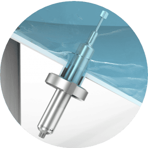
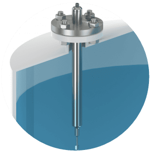 | 1. Long insertion from the top | SRD-X5-A370-BA20A Connection: Flange ANSI 2” 150lb RF |
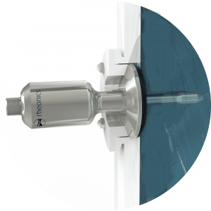 | 2. Flush installation | SRV-X4-15T Connection: 1.5” Tri-Clamp |
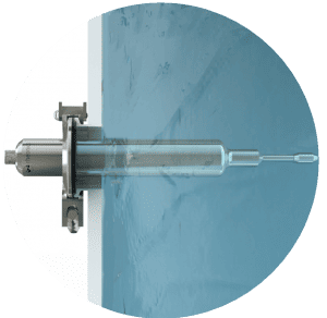 | 3. Long Tri-Clamp insertion on wall | SRV-X5-A200-B20T Connection: 2” Tri-Clamp |
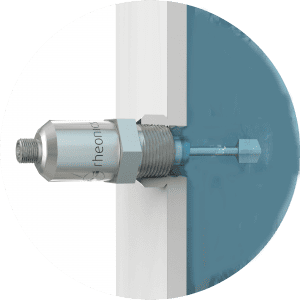 | 4. Threaded installation on wall | SRD-X1-34N Connection: NPT 3/4” |
 | 5. Long installation from bottom | SRD-X5-A150-BH50 Connection: DIN11851 DN50 |
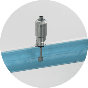 | 6. Threaded installation in pipe | SRD-X1-12G Connection: G 1/2” |
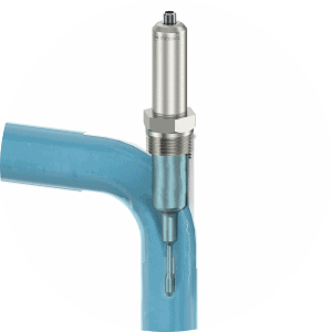 | 7. Long insertion threaded installation in pipe elbow | SRV-A130-B1N25 Connection: NPT 1.25” |
The Rheonics SRV and SRD sensors can be installed in tank for mixing processes if:
-
Shafts or rotating blades do NOT hit the sensor probe.
-
Shafts or rotating blades do NOT interfere with the sensing elements of the probes.
-
The sensor can be installed below the minimum fluid level in tank. This way, the sensing element of the probe will be always immersed in fluid.
Advantages of installation in tanks are:
-
Track the complete mixing process . It is possible to track the complete process from start to finish and to trace important events (such as the addition of solvents, temperature changes, start and stop of pumps and mixers) and see how these affect the viscosity or/and density of the fluid.
-
Versatility of installation: From the top, side wall, bottom of the tank, all installation points can be used for the Type-SR sensors. Installation of long insertion sensors have the advantage to avoid buildups or deposits around the sensing element by protuding the sensor further in the fluid.
Important consideration when installing in tank
-
Variable flow conditions: Fluid across the sensor is likely to not have a well defined flow behavior. Rheonics sensors don’t require a specific flow rate for good readings, but constant flow rates favor stable readings. Consider that for non-Newtonian fluids, viscosity will change with flow rate due to change in apparent shear on the fluid.
-
Higher noise: This is a possible issue with installations in tank, at least until the mixture is homogenous. However, the noise can be used as an indicator of homogeneity of the mixing.
-
More data processing: Installation in tank may need a deeper analysis from the user to get the baseline values and filters may be neede to reduce noise and track homogeneity. The RCP software of the sensor is a useful tool for data analysis and Rheonics sensors have multiple levels of filters available to monitor and output baseline values as well as short term variations. Contact Rheonics support to learn how onboard filters can be useful for your data captures.
-
Generally, the SRD is not recommended for mixing tanks due to the variable flow that affects the readings stability. Installation in recirculation line is preferred since the probe is exposed to a controlled flow.
The Rheonics SRV and SRD sensors can be installed in the recirculation lines for mixing processes if:
-
Fluid is recirculating in line during the mixing process.
-
We recommend to have the fluid in motion and at nearly constant flow velocity to ensure stable, repeatable and reproducible measurements in particular when the fluid is non-Newtonian. Moving fluid ensures that there is good transfer of the fluid over the sensor and it is measuring a representative sample of the tank. Constant flow rate ensures similar shear rate for non-Newtonian fluids, ensuring apparent viscosity is measured at similar shears between samples.
Advantages of installations in recirculation lines are:
-
Uniform flow conditions around the sensing element, which lead to constant and clean readings for viscosity.
-
Lower noise: This is a result of ensuring similar flow-induced shear rate for non-Newtonian fluids.
-
End-product detection: It is easier to ensure similarity of operating conditions (flow rate, temperature) in recirculation lines which means batch to batch comparison is done in similar conditions.
Two main criterias should be met for the installation of the SRV and SRD sensors:
i. Immerse the sensing element completely in the fluid.
ii. Avoid stagnation or deposits around the sensing element.
Rheonics SR sensors allow multiple installation options as shown in previous table. Let’s review each installation example closely.
Table 2: Detail of Installation Alternatives in Tank
| Installation | Considerations |
|---|---|
| 1. Long insertion installation from the top | Good solution if installation on walls or bottom is not possible due to insufficient space. Sensing element should be immersed in the fluid (see next image).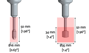 For open tanks, consider the TMA-34N Tank mount adapter from Rheonics as alternative solution. For the SRD: Full submersion ensures thermal balance along the resonator and ensures high accuracy of density. Read more here. |
| 2. Flush installation on tank | Avoids dead zones due to installation and favors cleanability. Consider using a welded flush flange for installation. For SRD: Density deviation may happen if there is a mismatch of ambient and fluid temperature. Read more here. |
| 3. Long insertion installation on wall | Avoids stagnation zones or deposits on sensor base from affecting the readings. Useful for thick or jacketed walls. User should ensure the sensing element is not in contact with any moving parts. |
| 4. Threaded short installation on tank | Standard version of the sensor. Most of the times, the simpler installation. Care should be taken during installation planning to ensure there are no dead zones around the sensing element that can lead to deposits around the sensing element. |
| 5. Long insertion installation from the bottom | Similar to installation variant number 3. Care should be taken to ensure drainability. |
| 6. Threaded installation in line | Rheonics offers NPT 3/4” and G1/2” threaded connections for short the sensor probe variant. Installation can be done with Rheonics weldolets For the SRV, perpendicular installation can be easily achieved with pipes from 2.5” up. For 1.5” and 2” pipes use Rheonics accessories. Special option for 1” is also available. For the SRD, perpendicular installation can be easily achieved with pipes from 2.5” up. Options for 2” pipes are available. Smaller sizes would require parallel installation with Rheonics flow cells. For the SRD, installation with short sensors is recommended for ambient tempature applications only. |
| 7. Installation in elbow line | Protudes the sensing element in the pipe, placing the tip axially to the fluid and good flow. Ideal scenario for fluids with high flow rate. For the SRD, this solution with long insertion probe installed parallel to flow is useful to mantain thermal equilibrium along the resonator and use in HT (high temperature) conditions. |
Both installation options, in tank or recirculation line, are valid and decision should be made based on the characteristics of the process and fluid.
It can be said that measurements directly in mixing vessel are much more valuable in long term but need more work from the process engineering on the costumer side. Installation itself requires more effort than in the recirculation line. Sensor needs a location where the best transfer of fluid can be offered, while trying to have uniform flow characteristics. Avoiding stagnation zones would be important in both cases.
Sensor Technology, Working principle and Applications
Viscometers
Density Meters