Key ways in viscosity & density measurements and management play central role in lube oil manufacturing steps are the following:
- Accurate blending operations and inline quality control
- Formulation and development of new lubricants
- Embedded testing
Introduction
Today’s lube oil market poses increasingly stringent product-quality requirements. Apart from automobile industry, chemical, construction, textile, infrastructure, agriculture, mining and oil drilling, construction, steel and cement, wind energy, marine, aerospace industries and energy sectors for engine oil, hydraulic oil, wire rope and bearings, are the key application areas where lubricants are utilized extensively. In the construction industry, lubricants are mainly used in earthmoving equipment owing to their anti-wear characteristics, excellent lubricity, and resistance to corrosion. Lubricants are also used as hydraulic fluids in the steel industry for various equipment including blast furnaces, bearings, pulley cranes, lifts, and engines, among others. Furthermore, lubricants are used in heavy-duty engine oils, axle and transmission oils, and greases.
Formulations are forever increasing in number and complexity. In addition to requirements for production agility, the Lube Oil Blending Plant (LOBP) has to face up to the margin pressures of a highly competitive lubricants market. Many customers now want on-demand deliveries and shorter lead times. This means lubricant blending plants may need to manufacture smaller batches. Achieving quality targets can be difficult, due to poor process control, human error, cross-contamination or raw material variability. The ability of a lubricant blending plant to maximise the productivity of assets, achieve on-specification blends every time and maintain flexibility to respond to changing market demands is of paramount importance.

What is lube oil blending?
The process of producing finished lubricants from base oils and additives is invariably described as oil blending rather than oil manufacture because there is no significant chemical reaction which takes place and blending is based predominantly on a mixing operation. However, the cost-effective operation of a modern blending plant is critically important to the overall process of delivering the correct lubricants of the correct quality and performance to customers. Blending lubricants may be relatively easy; operating a blending plant is certainly not.
Market Insights & Industrial Applications
The global lubricants market size is projected to reach USD 166 billion by 2025, according to a new report by Grand View Research, Inc. It is expected to expand at a CAGR of 3.7% during the forecast period. Rapidly growing sales of automobiles, primarily in countries such as India, China, U.S., and Brazil is driving the growth.

Segmentation of lubricants by application and some examples:
- Automotive Lubricants – Engine oils, gear oils, transmission fluids
- Industrial Lubricants – Hydraulic oils, compressor oils, gear oils
- Metalworking Fluids – Cutting fluids, EDM oils, Press & Rolling Oils
- Greases – For roller bearings, High Temperature greases, Gear Coupling greases, Biodegradable greases
- Marine Lubricants – Engine oils for piston engines, System Oils, Cylinder Oils
- Industrial & Private Engine Oils – For Diesel engines, for Gas engines, for HFO (Heavy Fuel Oil) engines
Segmentation by products:
- Mineral-oil based lubricants
- Synthetic lubricants
- Bio-based lubricants
Application
What problems occur if a lubricant’s viscosity is too high or too low?
If a lubricant’s viscosity is too high, the lubricant may have flowability concerns. This may result in:
- More friction and more heat, which
- accelerates the oxidation process, shortening the lubricant’s life;
- promotes varnish and sludge formation; and
- increases energy consumption, since more power may be needed to overcome the excessive heat and keep the system running in an appropriate temperature range
- Increased wear, which may translate into more downtime for repairs and shorter component life
- Poor cold-start pumpability, increasing the risk of equipment damage or failure at start-up
- Poor defoaming and poor demulsibility (water separability)
If a lubricant’s viscosity is too low, the fluid might not sufficiently coat and protect the parts as intended. The consequences may include:
- Excessive wear, leading to more repairs/replacement of component parts
- Greater friction and heat, promoting faster oxidation, increased varnish and sludge formation, and higher energy consumption
- Heightened vulnerability to component damage or failure, especially at high temperatures, high loads and low speeds
- Higher susceptibility to the impact of particle contamination
Robust and accurate viscosity measurement under harsh process conditions (replicated in testing) is essential to ensure the final product quality of lubricants when manufacturing and filling lubricant oils. Only a repeatable and accurate viscosity measurement during product production guarantees consistent product quality and saves production time.
Where do viscosity measurements add value in the chain?
Lube Oil Manufacturing: Blending
Various additives are blended into base oil to enhance its properties and formulate lube oil. The oil is mixed with additives to give it the desired physical properties (such as the ability to withstand low temperatures). Selection of additives is done according to desired lube oil specifications. For making any lube oil, basically 3 raw materials are used:
- Base oil
- Additives
- Viscosity Index Improver (Viscosity Modifier)
At this point, the lube oil is subjected to a variety of quality control tests that assess its viscosity.
Blending lubricants may appear to be relatively straightforward. However, there are two major problems that need to be considered:
- Avoiding the need to re-blend or correct an out-of-specification blend
- Minimising production of slop oil
Manual blending operations in manufacturing lubricants pose serious challenges in daily operations such as: long process times, low flexibility of recipe management and frequent operator interventions. These challenges had been directly linked to the productivity, profitability and safety of operations at the lubricant plant.
Formulating and developing a new industrial lubricant
The general methodology for developing a new or improved industrial lubricant is essentially the same as that for an automotive engine oil, with some differences. It is still expensive and time-consuming. Choosing the most suitable base oil(s) and additives is usually relatively easy.
Once an initial “best-guess” formulation has been selected, the first step is to test it in simple, low-cost laboratory tests. A wide number of viscosity & density tests become essential to assess the physical or chemical properties of lubricants. Tests for physical properties include low-temperature viscosity, high-temperature viscosity & density (specific gravity). Ability of formulation engineers to automatically run these prototype blended samples through the complete temperature cycle is vital to assess the strengths and weakness of the samples.
Quality Control
Most applications of lube oils require that they be non-resinous, pale-colored, odourless, and oxidation-resistant. Over a dozen physical and chemical tests are used to classify and determine the grade of lubricating oils. Common physical tests include measurements for viscosity, specific gravity, and color, while typical chemical tests include those for flash and fire points.
Probably the most important single property of a lubricating oil is its viscosity. A factor in the formation of lubricating films under both thick- and thin-film conditions, viscosity affects heat generation in bearings, cylinders and gears. It also determines the ease with which machines may be started under cold conditions, and it governs the sealing effect of the oil and the rate of consumption or loss. For any piece of equipment, the first essential for satisfactory results is to use an oil of proper viscosity to meet the operating conditions.
Various density & viscosity tests are required to assess the properties and performance of both base oils and additives used as raw materials with which to blend finished lubricants. Because a blending plant is another link in the entire supply chain, the ability of the blending plant staff to manufacture finished lubricants of the correct quality depends in part on the ability of the suppliers of base oils and additives to deliver the appropriate quality raw materials.
- For base oils, the standard methods for measuring kinematic viscosity are ASTM D445 and IP 71
- Low-temperature, low-shear viscosity is important for predicting the possibility of “air binding” in motor oils after vehicles have stood at low temperatures for a considerable period. The Brookfield method ASTM D5133 is believed to correlate with these problems, and it is recommended that this test is performed on new oil formulations. It is, however, time-consuming and does not readily permit tests on large numbers of samples, and so is not applicable for use in lubricant blending plants. For base oils, low-temperature flow properties are a better guide as to their suitability for use in automotive engine oils, automatic transmission fluids and some gear oils and hydraulic oils.

Embedded testing
Lubricants are complex and highly engineered fluids which perform a variety of protective and functional jobs – provide hydrodynamic film between moving components, including heat dispensing, suspending contaminants, acid neutralization, and preventing corrosion and so on. Lubricating oil in IC engines is exposed to various strains depending on the fuel quality, ambient conditions and the operating parameters which change its physical and chemical properties and ultimately degrade. In order to avoid an engine failure, the oil must be changed before it loses its protective properties. At the same time, an unnecessary oil change is unwanted because of environmental and economic reasons. In order to schedule oil change interval optimally, the actual physical and chemical condition of the oil needs to be monitored. The engine oil condition provides insight into the actual state of the engine and thus supports the early detection of possible engine failures.
Viscosity is considered as one of the most important parameters for the oil’s lubrication properties and its inclusion into the on-line monitoring systems has been recommended by several studies. Commonly chemical oil deterioration (e.g. due to oxidation) is associated with an increase in viscosity whereas mechanical wear (“cracking” of organic chain molecules) and fuel dilution lead to a decrease in viscosity. Therefore, knowledge of viscosity in real time provides significant benefit to measure aging of oil, ingress of contaminants during commercial operations and prevent incipient mechanical failure due to loss of oil lubrication properties.
Challenges with traditional process monitoring & quality control techniques
Blending & Quality Control
Sampling is a common & conventional technique of QC and monitoring the blending process. The success of sampling depends heavily on the type of sample bottles & sampling methods – amount, accuracy, reliability and utility of the data that can be acquired from the sample. Samples of base oils and additives need to be taken before blending, samples of blends may need to be taken during blending and samples of finished products will need to be taken following blending. A representative sample of each batch of blended lubricant must be taken, for process control, quality control and quality assurance purposes. It is very important that samples are taken while equipment is operating (whether blending or pumping), so that the sample is representative of the process being conducted. This method is labour & time intensive and is prone to errors & inaccuracies.
Embedded testing
In common practice, engine oil is changed at a constant time or mileage interval according to the recommendation of the lubricant oil manufacturers or OEMs. This oil changing method is not based on the real oil condition of the specific engine and may be replaced before reaching the end of its useful life or after its useful life is exceeded. This is uneconomical, as it will be a waste, and also deteriorate the engine.
In some lubricant monitoring techniques, such flexible oil drain intervals are determined by continuously monitoring characteristic engine and driving parameters (such as, e.g. driven distance, speed, and oil temperature). The proper oil drain interval is then estimated by corresponding algorithms processing these parameters. These algorithms are developed empirically by means of extensive field studies. The algorithms basically use said parameters to estimate the oil condition in an indirect way. These techniques do not monitor the physical properties of the lubricant directly, therefore critical problems such as fuel contamination can be overlooked. Excessive lubricant contamination may lead to dramatic changes in lubricant properties, preventing the lubricant from performing its required functions. However, ideally the evaluation of the oil condition should solely be based on parameters measured directly in the oil itself.
Conventional mechanical and electro-mechanical viscometers designed primarily for laboratory measurements are difficult to integrate into the control and monitoring environment. The current methodology of testing in off-site labs in not optimal and expensive due to the logistical challenges of shipping and high fixed costs. In lubricants industry, the Saybolt Standard Universal Viscometer is the standard instrument for determining viscosity of lubricants between 70- and 210-degrees Fahrenheit (21 and 99 degrees Celsius). Viscosity is measured in the Say bolt Universal second, which is the time in seconds required for 50 millilitres of oil to empty out of a Saybolt viscometer cup through a calibrated tube orifice at a given temperature. This method is highly dependent on operator experience, prone to errors and makes JIT production increasingly difficult.
Why is real time viscosity measurement for lube oil blend monitoring & QC important?
There are several motivational benefits from cost, environmental, and logistical perspectives to on-line real time viscosity measurements for lubricant blend monitoring & quality control. Viscosity automation in lube enhances process flexibility and performance to meet just-in-time requirements.
Key benefits are as follows:
- Avoid reblending for improved plant productivity and to avoid delays: Having to reblend should be avoided wherever possible. Reblending means using additional energy (a significant cost) and a potential reduction in the annual capacity of the blending plant. Reblending may also mean keeping a customer waiting for the delivery of a key product. Automated blending systems with inline viscosity management enable effective quality control of raw materials, eliminate the need for reblending and optimise end lube oil quality.
- Reduction in manual interventions and operating expenses: In a lubricant blending plant, operating expenses are generated heavily due to the manual involvement (supervision and operation) required in routine processes. The time taken to complete a blend has a significant effect on the efficiency and cost-effectiveness of a blending plant. Replacing conventional viscosity measurement devices with robust viscometers makes QC easier & more reliable.
- Stay in control of the blending process & achieve optimal blending time for best product quality and maximum cost savings: If a blend is mixed too quickly, it may not be completely homogeneous (and so be off specification) and the mixing time will have to be extended. If too much time is spent mixing a blend, energy will have been wasted (in both mixing and heating) and the blending equipment will not have been available for the next blend. Inline viscosity measurements during lube blending process
- Logistical advantages: On line lube viscosity analysis would reduce the number of samples sent to off-site laboratories, and the involved costs. Continuous condition outputs from onsite analyses would also reduce shipping labour/costs and sampling error.
- Faster response times: In-situ viscosity analysis would reduce/eliminate the delay between sampling and receiving a response from the laboratory.
- Accurate information: The true value of real-time data trending is that it provides a window into the mixing system. In embedded testing, real time viscosity monitoring techniques quantify changes in the physical properties of the lubricant and give a more accurate reading of the oil condition, thereby reducing oil consumption and providing the means to diagnose component failure.
- Environment: Utilisation of oil can be maximised through on-line monitoring systems, thus resulting in reduced wastage which is good for the environment.
Rheonics’ Solutions for Quality control and assurance of refinery processes
Automated, real time in-line viscosity measurement is critical to oil condition monitoring. Rheonics offers the following solutions, based on a balanced torsional resonator, for process control and optimisation in the real time engine oil condition monitoring:
- In-line Viscosity measurements: Rheonics’ SRV is a is a wide range, in-line viscosity measurement device with inbuilt fluid temperature measurement and is capable of detecting viscosity changes within any process stream in real time.
- In-line Viscosity and Density measurements: Rheonics’ SRD is an in-line simultaneous density and viscosity measurement instrument with inbuilt fluid temperature measurement. If density measurement is important for your operations, SRD is the best sensor to cater to your needs, with operational capabilities similar to the SRV along with accurate density measurements.
Continuous blending processes require “on-spec” material to be made as quickly as possible. Rheonics’ in-line blending solution assures a constant on-specification product with optimum equipment usage and minimal operator interaction. This allows you to run at maximum rates with automatic adjustments and that reduces blend times without sacrificing quality.
Automated in-line viscosity measurement through SRV or an SRD eliminates the variations in sample taking and lab techniques which are used for viscosity measurement by the traditional methods. The sensor is located in-line so that it continuously measures the lubricant viscosity (and density in case of SRD). Both the sensors have a compact form factor for simple OEM and retrofit installation. They require no maintenance or re-configurations. Both the sensors offer accurate, repeatable results no matter how or where they are mounted, without any need for special chambers, rubber seals or mechanical protection. Using no consumables, SRV and SRD are extremely easy to operate.
Key features of SRV & SRD:
- Menu-driven electronic controls are powerful and easy to use.
- Built-in temperature monitoring using a high accuracy PT1000 RTD.
- Multiple output signals – displays temperature and temperature-compensated viscosity
- Automatic viscosity control – the sensors are pre-set but
- Data logging – date and time-code are automatically logged, creating an audit trail and simplifying performance and quality trend measurement.
- Security and alerts – designed to prevent unauthorized changes and sound an alarm when setpoints are reached so operators can take action quickly.
- Quick-change memory settings – for process lines that run more than one fluid, this feature simplifies changing settings.
Supporting formulation engineers in the Labs
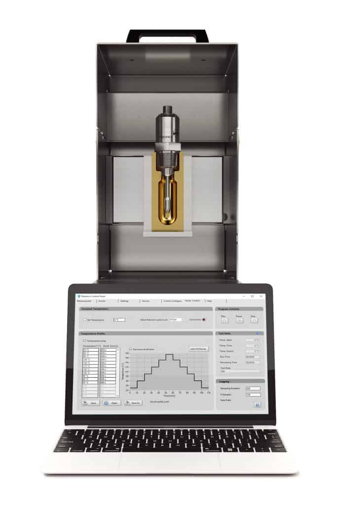
Even though the SRV sensor is built to ensure complete quality control of blended lube in production. The same sensor is also used in lab setting for formulation research. Rheonics standalone thermal modules are used by formulation engineers to rapidly test new samples across the complete thermal operation range. STCM is built to specifically work with SRV and SRD, The equipment is the same size as a small tabletop coffee machine and has solid state heating and cooling to achieve the full operational range.
The underlying principle is possible to use as a carousel based automated sampling and test system. A key advantage of using the SRV for formulation research is that the same sensor is then installed on the incoming raw material check, pilot plants and final production lines so there is no discrepancy in the measurement system used across the complete lubrication ecosystem.
Rheonics' Advantage
Compact form factor, no moving parts and require no maintenance
Rheonics’ SRV and SRD have a very small form factor for simple OEM and retrofit installation. They enable easy integration in any process stream. They are easy to clean and require no maintenance or re-configurations. They have a small footprint enabling Inline installation in any process line, avoiding any additional space or adapter requirement.
High stability and insensitive to mounting conditions: Any configuration possible
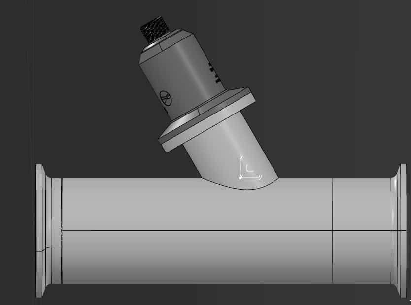
Rheonics SRV and SRD use unique patented co-axial resonator, in which two ends of the sensors twist in opposite directions, cancelling out reaction torques on their mounting and hence making them completely insensitive to mounting conditions and flow rates. Sensor element sits directly in the fluid, with no special housing or protective cage requirements.
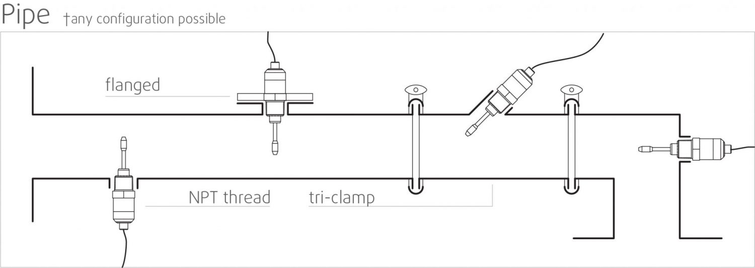 Mounting - Pipes
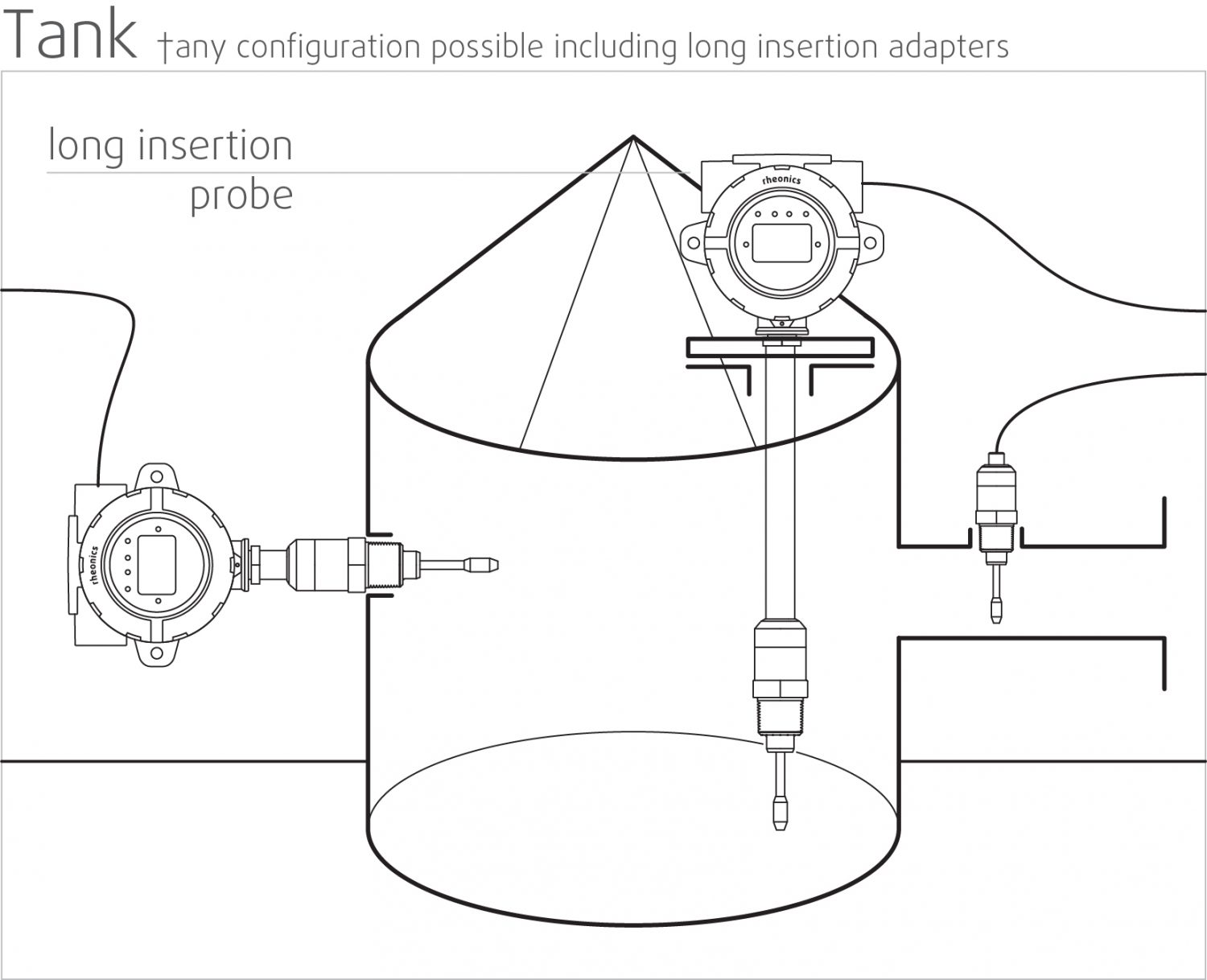 Mounting - Tanks
Instant accurate readouts on production quality – Complete system overview and predictive control
Rheonics’ RheoPulse software is powerful, intuitive and convenient to use. Real-time process fluid can be monitored on the integrated IPC or an external computer. Multiple sensors spread across the plant are managed from a single dashboard. No effect of pressure pulsation from pumping on sensor operation or measurement accuracy. No effect of vibration.
Inline measurements, no bypass line is needed
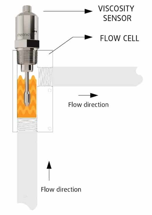
Directly install the sensor in your process stream to do real time viscosity (and density) measurements. No bypass line is required: the sensor can be immersed in-line; flow rate and vibrations do not affect the measurement stability and accuracy.
Easy installation and no reconfigurations/recalibrations needed – zero maintenance/down-times
In the unlikely event of a damaged sensor, replace sensors without replacing or re-programming electronics. Drop-in replacements for both sensor and electronics without any firmware updates or calibration changes. Easy mounting. Available with standard and custom process connections like NPT, Tri-Clamp, DIN 11851, Flange, Varinline and other sanitary and hygienic connections. No special chambers. Easily removed for cleaning or inspection. SRV is also available with DIN11851 and tri-clamp connection for easy mounting and dis-mounting. SRV probes are hermetically sealed for Clean-in-place (CIP) and supports high pressure wash with IP69K M12 connectors.
Rheonics instruments have stainless steel probes, and optionally provide protective coatings for special situations.
Low power consumption
24V DC power supply with less than 0.1 A current draw during normal operation.
Fast response time and temperature compensated viscosity
Ultra-fast and robust electronics, combined with comprehensive computational models, make Rheonics devices one of the fastest, versatile and most accurate in the industry. SRV and SRD give real-time, accurate viscosity (and density for SRD) measurements every second and are not affected by flow rate variations!
Wide operational capabilities
Rheonics’ instruments are built to make measurements in the most challenging conditions.
- Pressure range up to 5000 psi
- Temperature range from -40 up to 200°C
SRV has the widest operational range in the market for inline process viscometer:
- Viscosity range: 0.5 cP up to 50,000 cP
SRD: Single instrument, triple function – Viscosity, Temperature and Density
Rheonics’ SRD is a unique product that replaces three different instruments for viscosity, density and temperature measurements. It eliminates the difficulty of co-locating three different instruments and delivers extremely accurate and repeatable measurements in harshest of conditions.
- Viscosity range: 0.5 cP up to 3,000 cP
- Density range: 0 up to 4 g/cc (0 to 4000 kg/m3)
Achieve accurate lubricant quality information through direct measurements, cut down costs and enhance productivity
Integrate an SRV/SRD in the process line to schedule lubricant change intervals optimally and achieve significant cost savings. Compared to the indirect approach of using algorithms to predict the real state, lubricant viscosity measurements would yield a true physical picture of the lubrication allowing the detection of possible approaching bearing/engine failures or abnormal states. And at the end of it all, it contributes to a better bottom line and a better environment!
Clean in place (CIP)
SRV (and SRD) are self-cleaning sensors – using the in-line fluid to clean the sensor while it is taking measurements reduces unscheduled maintenance. Any small residue is detected by the sensor, enabling the operator to decide when the line is clean for purpose. Alternatively, these sensors provide information to the automated cleaning system to ensure full and repeatable cleaning between production runs.
Superior sensor design and technology
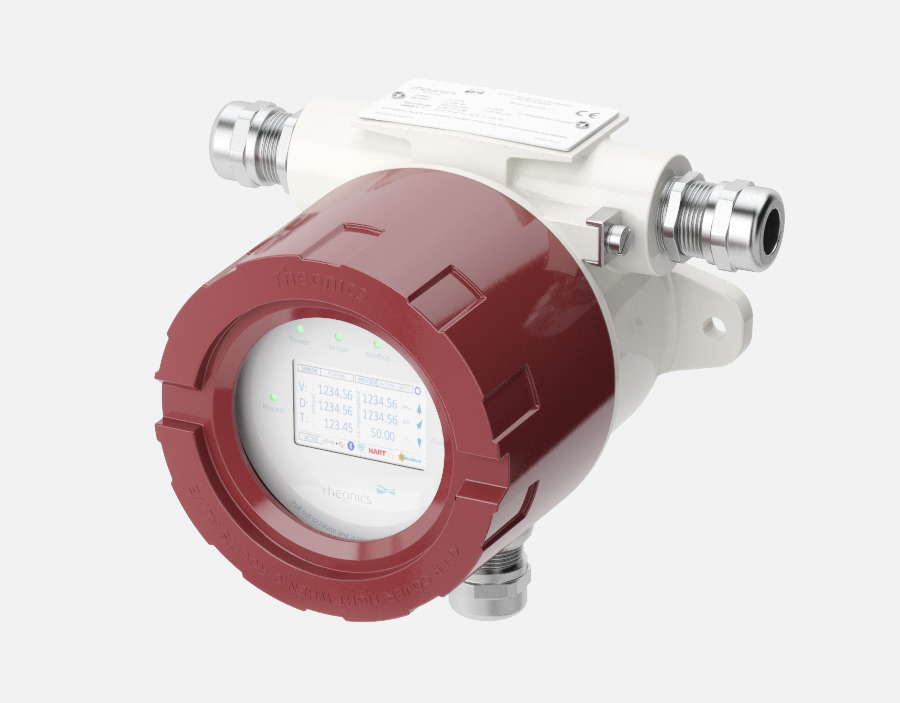
Sophisticated, patented 3rd generation electronics drive these sensors and evaluate their response. SRV and SRD are available with industry standard process connections like ¾” NPT and 1” Tri-clamp allowing operators to replace an existing temperature sensor in their process line with SRV/SRD giving highly valuable and actionable process fluid information like viscosity besides an accurate measurement of temperature using an in-build Pt1000 (DIN EN 60751 Class AA, A, B available).
Electronics built to fit your needs
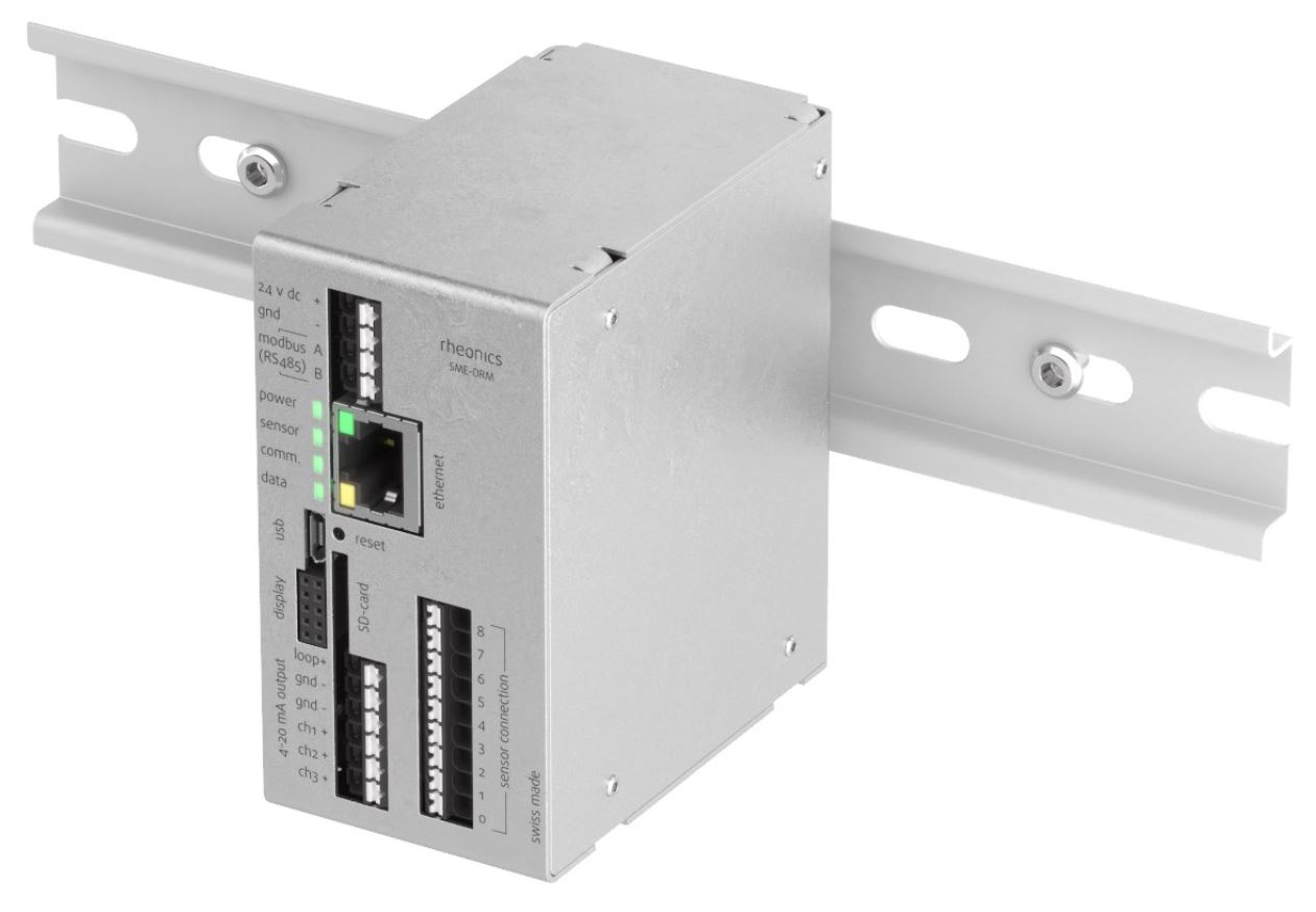
Available in both a transmitter housing and a small-form factor DIN rail mount, the sensor electronics enables easy integration into process pipelines and inside equipment cabinets of machines.
Manage blending more efficiently, cut down costs and enhance productivity
Integrate an SRV in the process line and ensure consistency over the years. SRV constantly monitors and controls viscosity (and density in case of SRD) and activates valves adaptively for dosing the mixture constituents. Optimise the process with an SRV and experience fewer shutdowns, lower energy consumption, lesser non-compliances and material cost savings. And at the end of it all, it contributes to a better bottom line and a better environment!
Superior sensor design and technology
Sophisticated, patented electronics is the brain of these sensors. SRV and SRD are available with industry standard process connections like ¾” NPT, DIN 11851, Flange and Tri-clamp allowing operators to replace an existing temperature sensor in their process line with SRV/SRD giving highly valuable and actionable process fluid information like viscosity besides an accurate measurement of temperature using an in-build Pt1000 (DIN EN 60751 Class AA, A, B available).
Electronics built to fit your needs
Available in both a transmitter housing and a small-form factor DIN rail mount, the sensor electronics enables easy integration into process lines and inside equipment cabinets of machines.
Easy to integrate
Multiple Analog and digital communication methods implemented in the sensor electronics makes connecting to industrial PLC and control systems straightforward and simple.
Analog and Digital Communication Options

Optional Digital Communication Options

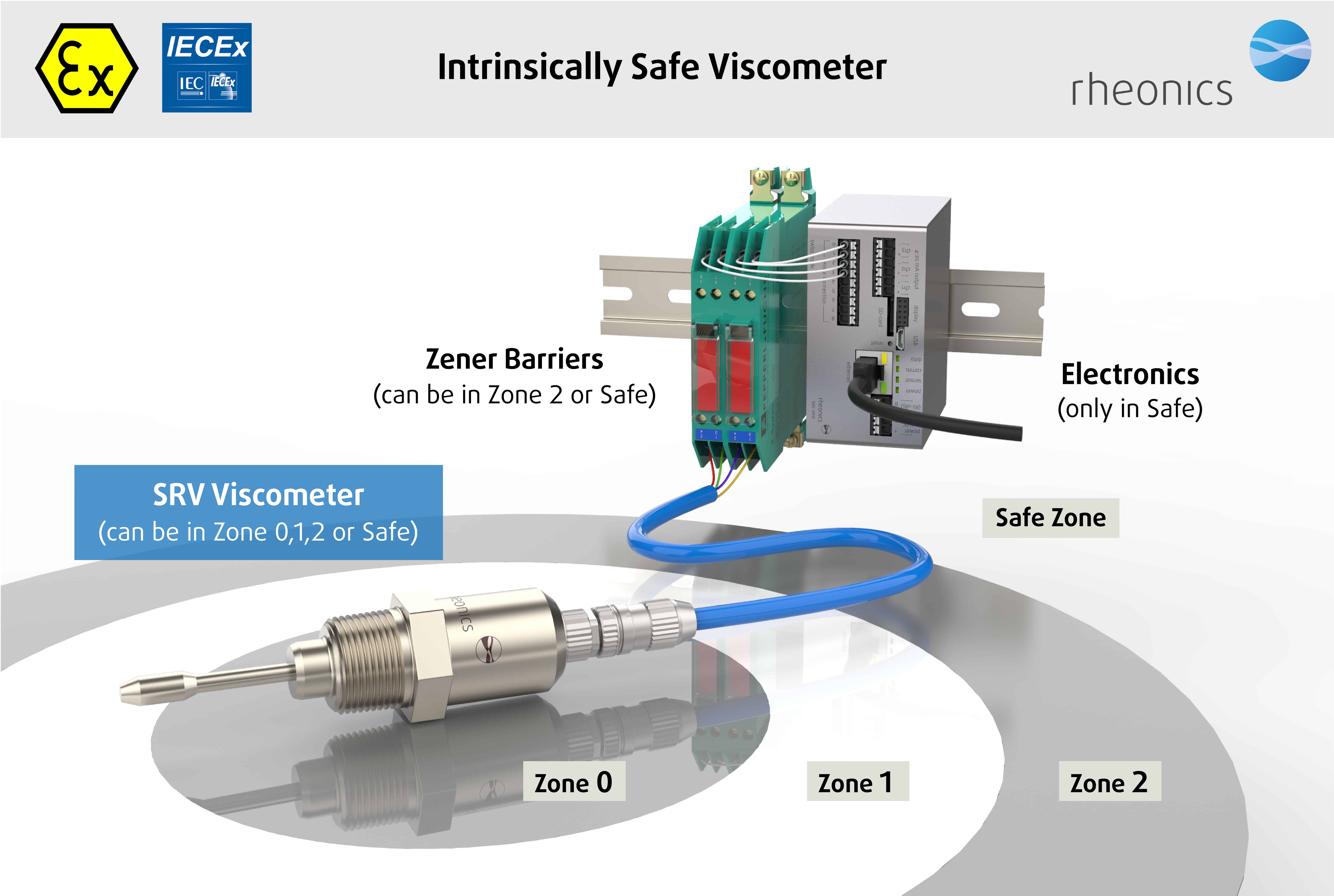
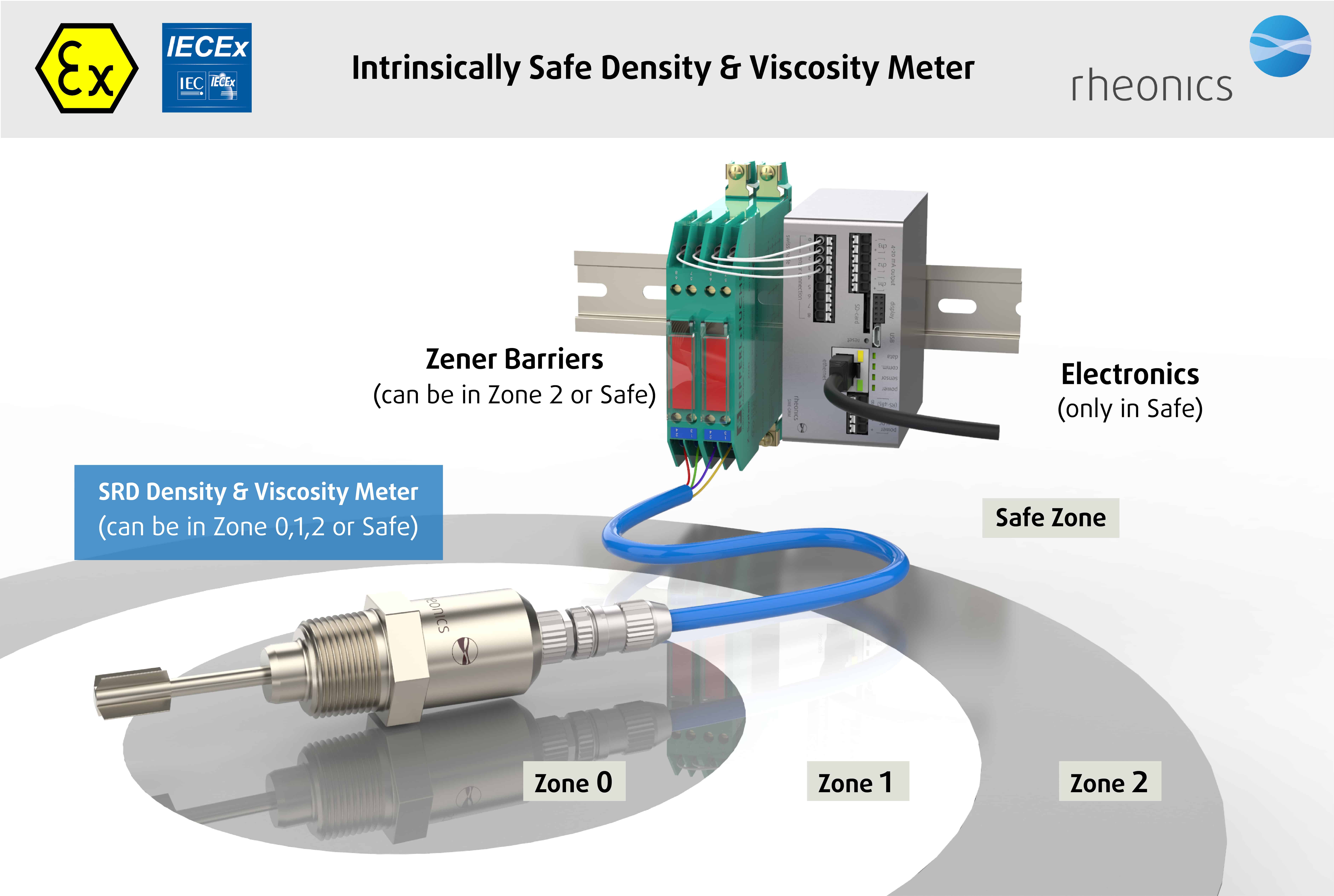
ATEX & IECEx Compliance
Rheonics offers intrinsically safe sensors certified by ATEX and IECEx for use in hazardous environments. These sensors comply with the essential health and safety requirements relating to the design and construction of equipment and protective systems intended for use in potentially explosive atmospheres.
The intrinsically safe and explosion proof certifications held by Rheonics also allows for customization of an existing sensor, allowing our customers to avoid the time and costs associated with identifying and testing an alternative. Custom sensors can be provided for applications that require one unit up to thousands of units; with lead-times of weeks versus months.


Implementation
Directly install the sensor in your process stream to do real-time viscosity and density measurements. No bypass line is required: the sensor can be immersed in-line; flow rate and vibrations do not affect the measurement stability and accuracy. Optimize mixing performance by providing repeated, consecutive, and consistent tests on the fluid.
In-line Quality control locations
- In tanks
- In the connecting pipes between various processing containers
Instruments/Sensors
SRV Viscometer OR an SRD for additional density
Rheonics Instrument Selection
Rheonics designs, manufactures and markets innovative fluid sensing and monitoring systems. Precision built in Switzerland, Rheonics’ in-line viscometers and density meters have the sensitivity demanded by the application and the reliability needed to survive in a harsh operating environment. Stable results – even under adverse flow conditions. No effect of pressure drop or flow rate. It is equally well suited to quality control measurements in the laboratory. No need to change any component or parameter to measure across full range.
Suggested product(s) for the Application
- Wide viscosity range – monitor the complete process
- Repeatable measurements in both Newtonian and non-Newtonian fluids, single phase and multi-phase fluids
- Hermetically sealed, all stainless steel 316L wetted parts
- Built in fluid temperature measurement
- Compact form-factor for simple installation in existing process lines
- Easy to clean, no maintenance or re-configurations needed
- Single instrument for process density, viscosity and temperature measurement
- Repeatable measurements in both newtonian and non-newtonian fluids, single phase and multi-phase fluids
- All metal (316L Stainless Steel) construction
- Built in fluid temperature measurement
- Compact form-factor for simple installation in existing pipes
- Easy to clean, no maintenance or re-configurations needed


