The ability to monitor the level of sand in desanders, separators, and flowback systems allows for automation and higher efficiency of sand removal processes and improved usage and lifetime of equipment.
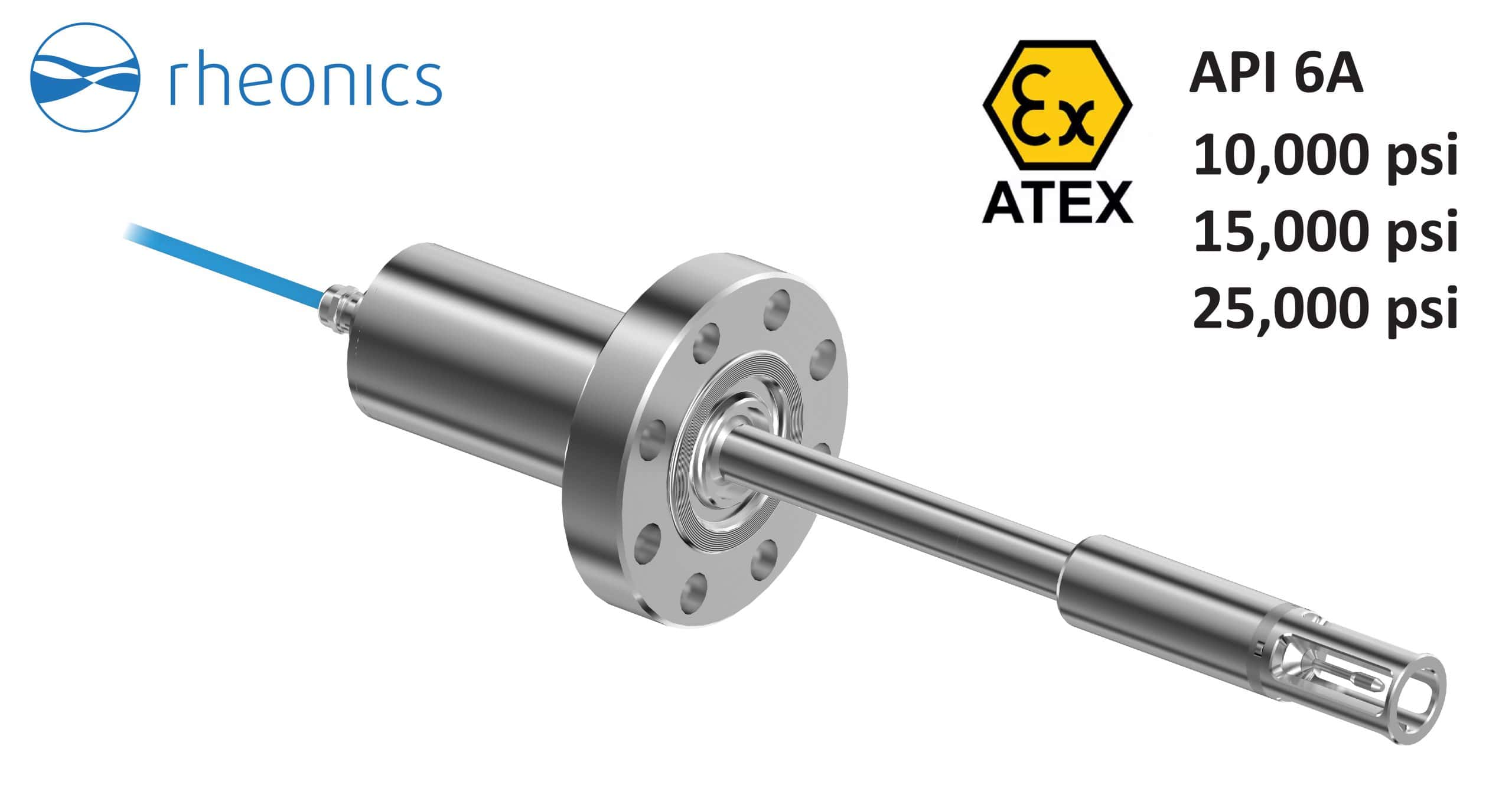
Table of Content
- Introduction
- Sand Management level monitoring and control
- Different strategies for sand monitoring
- Rheonics SDP – Sand Detection Probe
Introduction
Sand production is one of the major concerns in the Oil and Gas Industry. The sand is created from the fluids and rocks extracted from wells. As a consequence of sand presence, the overall transport and transformation process is affected by deterioration in equipment (wellbore, pipelines, tubing, valves, choke, separator), production stops, decrease in production rate, early maintenance, etc. High economic efforts are therefore put into sand management and control in the field.
Sand production is an issue present on the Upstream side of Oil and Gas, which deals with the exploration, extraction, and production of crude oil and gas. After a well is drilled and vetted with economically extractable quantity of hydrocarbons, wellheads are used to control the extraction rate and conditions. Single or multiphase separators are then used to obtain the hydrocarbons needed for refining or processing, which is known as the Downstream side of the industry.
This article describes the Rheonics Sand Detection SDP sensor and how it is used to monitor the sand level in the sand separation equipment, allowing quick actions for better sand management.
Rheonics sensors are also used for mud weight monitoring of drilling fluids in realtime on rig sites.
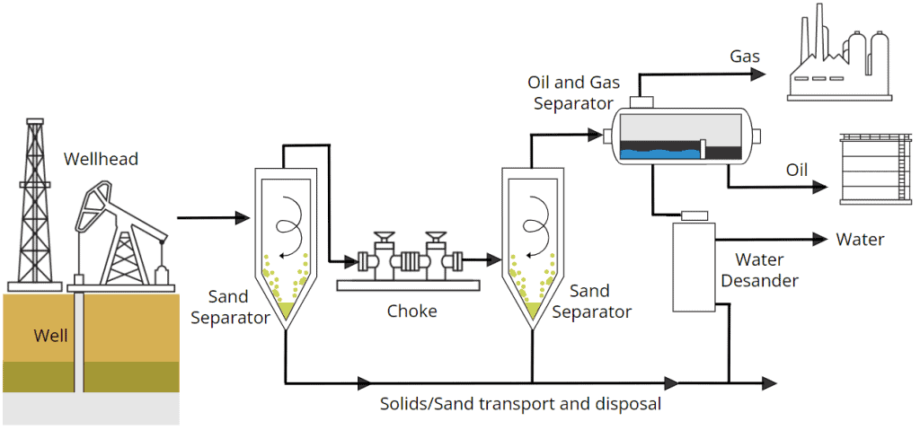
Figure 1: Oil and Gas extraction and sand production overview
Sand Management level monitoring and control
Sand Management relates to the “Sand life cycle”, which includes procedures such as initial modelled predictions, actual monitoring, and final disposal of sand accumulation, considering the environmental, safety, and economic aspects.
During sand management required actions are: separation, collection, cleaning, measurement, and monitoring.
Sand Separators
Separation is a process used to isolate solids from liquid contained in the multiphase fluid coming from the well. Equipment used for sand separation, aka. Desanders, can be gravity vessels (i.e., free water knockout (FWKO) with a sand jet), sand trap desanding, hydro cyclone, or filter systems.
These desanders vary in designs, sizes, and working principles. The selection depends on the required capacity, flow rate, solids size, location in the production line, economic impact, etc. There are different stlye of desanders suited for specific use case like multi-liner desander, insert desander, etc.
Wellhead desander are multiphase soild-fluid cyclone separators designed to treat full wellstream flow. They can work with mixed oil, gas, water streams and can operate at full gas void fractions and are used in both gas and oil wells. They are used for both handling temporary solids production during well testing and clean-up as well as for permanent ongoing sand production processing. They are built to meet ASME and API-6A design ratings.
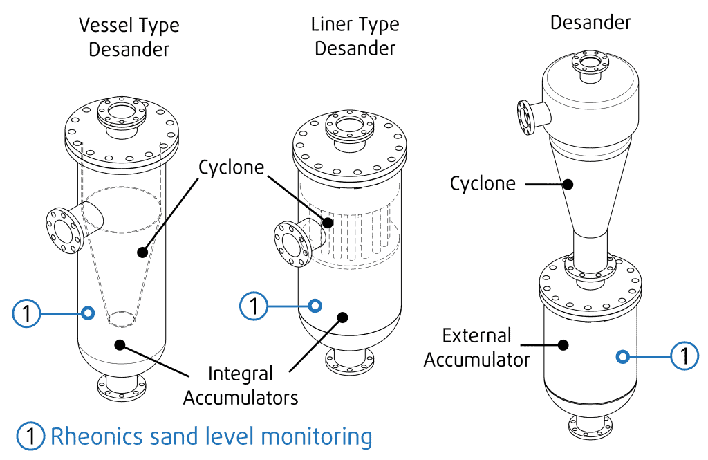
The next figure shows common desanders used in different locations and where inline Rheonics sensors can be used.
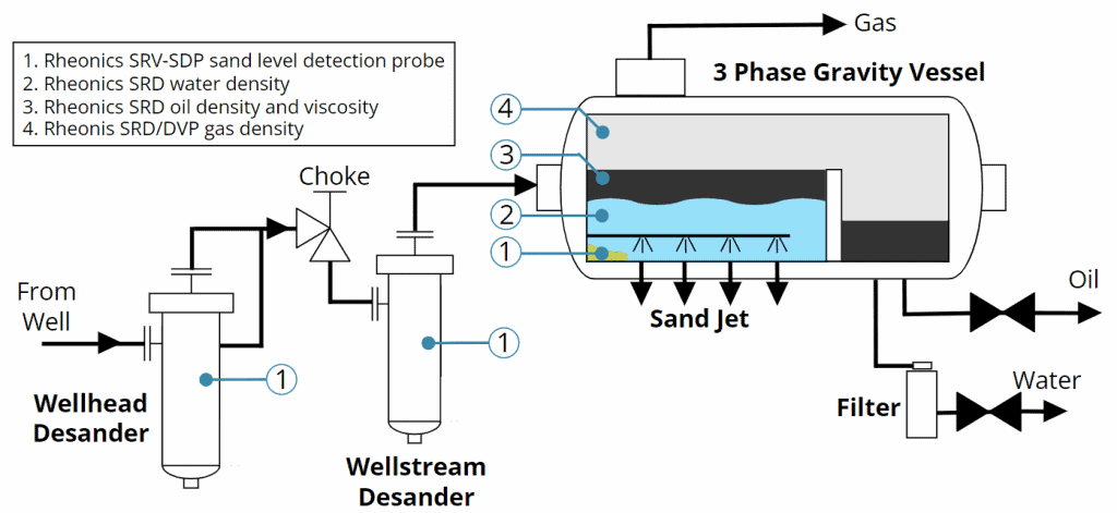
Installation of a desander can be defined by its location related to the choke valve. Choke valves are used to control the flow rate and pressure in the line. Desanders located before the choke or at the wellhead, protect all equipment downstream (including the wellhead choke) but require high-pressure design. Desanders located after the choke require much lower pressure ratings, may be cheaper, but will not protect the choke (maintenance or replacement required), and are usually bigger in dimensions.
An additional advantage of desanders installed before the wellhead choke is that the filtered sand is usually cleaner, with a low percentage of hydrocarbons (up to 0.5% of concentration by weight – kg oil per kg dry sand) [5].
Hydrocyclones:
A cyclonic separator device, also called “desanders”, “desanding cyclone“ or “desanding hydrocyclone“, uses a swirling flow with the effluent multi-phase fluid to capture and separate solids. The centrifugal forces force solids, like sand, to move near the wall and are pulled down by gravity along the conical-shaped vessel as underflow. During this process, a flow of clean fluid, water, or hydrocarbons is induced to exit the vessel through the top, at the center of the swirling flow.
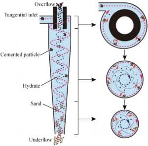
The underflow with the solids filtered is stored in an accumulation section below, that may be integral or separated from the cyclone.
A known issue with cyclonic separators is the accumulation or solidification of sand that can plug the system. This can happen if the rate at which the sand is created exceeds the rate at which the sand is removed through pipes and valves. Dump valves with a predefined open cycle are ineffective since the sand formation can be non-constant and often varies. If the valve opens when no sand is formed, the multi-phase effluent fluid can directly go through the underflow, losing the product. If is opens too late, sand will fill the vessel, compromising overall operations.
Leaving the accumulator discharge valve open a little has continuous liquid loss and erosion on the discharge valve. For low pressure operation (<100 psig at the inlet) this method of operation is often used. However, for high pressure operation (>100 psig), or multiphase flow with oil in the fluid stream, or very abrasive solids, or problems with handling large volumes of discharged liquids – cracking open the discharge valve is not a reasonable solution (4).
An improved solution is to use flux lines or flow lines in the vessel. Using pressure sensors, the pressure difference created by the accumulation of sand can be detected and the flux line creates a downward flow avoiding sand plugging. These are however also ineffective if the sand creation rate is too high.
Operators can monitor sand production in separators and any other equipment, using a variety of techniques, such as analyzing fluid samples, numerical simulations and other indirect measurement techniques besides direct sand level measuring sensors like Rheonics Sand Detection Probe SDP. The objective in all these cases is to identify and address sand production problems early on and in some cases to automate the removal of sand.
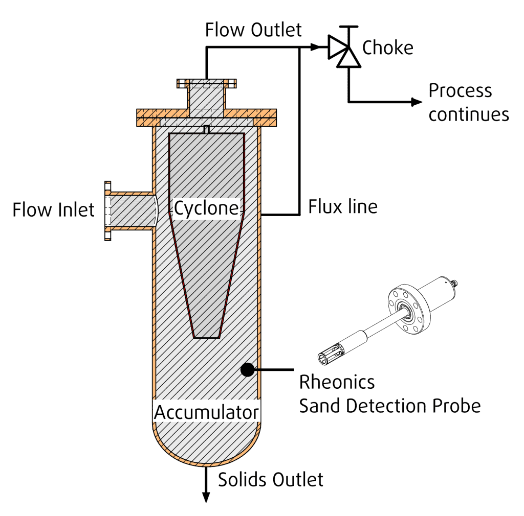
Figure 5: Flux line in desanders
Need for real-time monitoring of sand level
Using equipment to monitor the sand level or concentration allows the user to:
- Identify sand accumulations without human intervention
- Schedule maintenance and cleaning of equipment
- Take action early on (before sand deposits cause serious damage)
- Plan process improvements
- Analyze tendencies of the rate of erosion
- Stabilize basements for full automation control
- Reduce the need for visual checks and human supervision
- Improve safety of operation and safety of personnel onsite
Different strategies for sand monitoring
Some technologies used for sand monitoring are listed in the next table.
Table 1: Sensor technologies for sand monitoring
| Technology | Description | Pros | Cons |
|---|---|---|---|
| Acoustic sensors | Non-intrusive Measures the sound waves generated by sand due to particles hitting the surface of a wellbore, pipeline, or any equipment | Easy to install in multiple points of production. Useful to identify concentration locations and, up to some level, the size of particles. | Affected by fluid flow, bubbles, external vibration, etc. Hard to calibrate - lack of reliable calibration equipment. Does not work at high pressures or when there are deposits on the transducer. |
| Erosion probes | Intrusive and invasive probe. Measures the electrical resistance differences due to the loss of material from the probe’s metal surface caused by sand impact. | Provides direct and quantitative information on the amount and distribution of sand production. Used as a sample of potential damage to the equipment. | Affected by corrosion, fouling, or plugging. Performance and durability are compromised. Needs close monitoring for replacement. Measurement sensitivity is compromised due to process artefacts. |
| Sand concentration sensor | Measures the electrical resistance or capacitance of the fluid, expected to relate to sand concentration and mass flow rate in the fluid. | Offers continuous and real-time data Alerts any changes or anomalies. | Influenced by other properties of fluid, such as temperature, pressure, and salinity Measurement sensitivity and confidence is severely affected by process artefacts like deposits |
| Ultrasonic probes | Not intrusive or invasive The sensor works by sending out sound waves and determines the time in which they return. Works like a radar to determine if solids are formed in a certain section of equipment. | Provides real-time information without being intrusive Handles vibration, infrared radiation, ambient noise, and EMI (Electromagnetic interference )radiation | Readings can be affected by the external properties of fluids Requires in-field calibration for each installation unless a specific flow cell or housing is used Severly affected by wall deposits and need re-calibration to work with changing vessel wall conditions |
| Vibration probes | Intrusive and invasive Operates at a certain frequency and detects the changes or deviations of frequency when it is in contact with fluid and solids. | Detects build-ups over time Can be set as a level alarm Can detect corrosion | Can be plugged by deposits |
| Nuclear Radiometric probes | Non-intrusive Based on gamma radiation detection, it counts how much radiation is achieved in a certain area over a fixed time to calculate the solid or material content | Works through thick metal Suitable for high pressure, corrosive and abrasive environments | Needs regular calibration High costs Regulations due to nuclear source, not allowed in some places |
Rheonics SDP - Sand Detection Probe
Rheonics SDP is an inline sand detection probe from Rheonics. The SDP sensor is used along with Ostrich software (Rheonics Sand Level Detection Software) for live infield detection of sand in separator equipment, including cyclone separators.
Rheonics SDP can be used to monitor the sand level in oil and gas industry equipment such as separators. This helps to protect production elements on the surface (oil and gas) and subsea side (subsea equipment).
The sensor operation is based on a torsional resonator that detects the changes in viscosity and density of a single- or multi-phase fluid. The sensor perceives the damping induced by the fluid in which it is immersed and its impact on resonant frequency.
The SDP is configured to sustain the working conditions of the system, for high pressures of up to 10K psi, with versions available for 15K psi and 25K psi. The sensor probe could also be mounted with different process connections like API flanges, Grayloc, Hammer Union, etc. This helps in the integration of the SDP sensor into different desanders and upstream or midstream pipelines and reservoirs.
Table 2: Specifications Rheonics Sand Detection Probe – SDP
| Rheonics Sand Detection Probe - SDP | |
|---|---|
| Extension Length | Customizable |
| Process Connection | Customizable |
| Max. Pressure Rating Variants | 10,000 psi (690 bar, 69 MPa) 15,000 psi (1035 bar, 103 MPa) 25,000 psi (1724 bar, 172 MPa) |
| Material | Stainless Steel 316 Hastelloy C22 available for high corrosion environment |
| Certifications | Ex (ATEX, IECEx, JPEx, etc. ) |
| Drawing | Rheonics SDP Drawing |
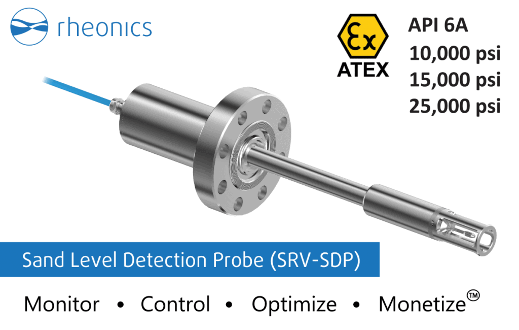
Figure 6: Rheonics SDP – Sand Detection Probe
Visit the next article to learn about an installation case of the SRD Density and Viscosity Meter in oil and gas pipelines along the API standards.
Sand Level Detection Probe SDP Installation
As shown in Figures 2, 4, and 5, the SDP sensor can be installed in different points, or desander types, of the oil and gas upstream section.
The SDP sensor can be used to detect the presence of sand or particles that could “cement” and plug the underflow outlet on desanders. The sensor is placed at a predefined height in the desander that would indicate if the level and volume of sand are high enough to alert that action is needed from the controller (e.g. PLC) and actuator (e.g. valve) to remove the sand. Two probes can be used to signal low and high levels for better automation of sand removal valve control and avoiding any fluid from exiting the vessel in the solids outlet line.
The SDP readings of sand level provide information on the level of solid deposits in a multi-phased fluid. For example, if the fluid is mainly composed of water, the sensor outputs a reading of approximately 1-2cP. But when additional particles or fluids are presented (i.e. sand, oil, etc.), the readings change significantly.
Applications:
Automate accumulator solids removal in Desanders and separators used for
- Oil and gas drilling
- Produced sand removal
- Well testing operations
- Coiled tubing cleanup
- Underbalanced drilling operations
- Waste water treatment
- Industrial process water treatment
- Stormwater runoff treatment
- Desalination plant
- Recycling facility
Benefits:
- Compact, robust design
- No moving part, zero maintenance or servicing
- Reduces cost of operating desander, making high-sand producing well production economical
- Reduces solids erosion of accumulator discharge valve through event based activation
- Helps reduce oil contamination of sand preventing sludge formation and alleviates difficult solids accumulation problems
Operations:
- Available in a wide range of size and pressure rating
- Available with ASME and API 6-A compliant flanges and other process connections
- No onsite commissioning or calibration needed
- Comes with Sand Level monitoring software with easy to set alerts and alarm levels
- Possible to also activate the accumulator discharge valve directly from the sensor system
- No operating pressure loss due to installation of sensor in desander or accumulator
Installation & Support:
- Easy to install
- Sensor probe built to fit any port on the desander
- EX certified
- No need for commissioning or calibration
- Test mode to check operation and sensitivity of the sensor
- Global support with remote diagnosis and configuration of the sensors
Automated Sand Removal System
The Rheonics sand level detection probe, SDP, leads the way for automated removal of sand accumulations in desanders and separators used in the Oil and Gas Industry. This is done by detecting the presence in line of sand or solids before they cause serious damages to the equipment, and sending a signal to activate a valve in the underflow line for sand transport and later removal.
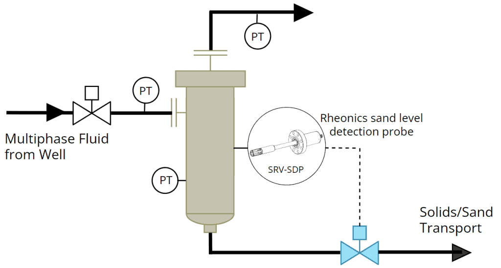
Figure 7: Sand Removal Control with Rheonics SDP Sand Detection Probe
How to order?
Use the online Request for Quotation RFQ for SDP and select the required information. Main configuration codes for sensor are detailed next.


| How to Order Rheonics Sand Detector Probe? | |||
|---|---|---|---|
| 1 | Rheonics SDP sensor SDP: Sand Detector Probe | 4 | Sensor Variant X9: Special installation adapter/sleeve. |
| 2 | Temperature rating Tx - Temperature rating (Max. operational) T1: Rated for fluids up to 125 °C (250 °F) T2: Rated for fluids up to 150 °C (300 °F) T3: Rated for fluids up to 175 °C (350 °F) T4: Rated for fluids up to 250 °C (480 °F) T5: Rated for fluids up to 285 °C (545 °F) | 5 | Insertion Length "A" Distance from flange to sensor tip. Defined by client, e.g. A500: 500 mm |
| 3 | Pressure rating PX - Pressure rating (max. operational) P1: Rated up to 15 bar (200 psi) P2: Rated up to 70 bar (1000 psi) P3: Rated up to 200 bar (3000 psi) P4: Rated up to 350 bar (5000 psi) P5: Rated up to 500 bar (7500 psi) P6: Rated up to 750 bar (10000 psi) P7: Rated up to 1000 bar (15000 psi) P8: Rated up to 1500 bar (20000 psi) | 6 | Process Connection "B" Process connection to be defined by client. Specify Norm/Standard and size. Send drawing if needed. Code given by Rheonics e.g. BAP0501: API Hub 16A 5000 psi Clamp number 1 |
| 7 | Sensor cable length Cable length defined in meters, e.g. CAB50: Standard cable 50 m (160 ft) | ||
DeSander and Separator Manufacturers
Numerous companies manufacture and operate Desanders catering to various industrial applications. Some of them are:
- GN Solids Control
- Derrick Corporation
- Sulzer
- Schlumberger
- Expro
- FMC Technip
- eProcess technology
- FLSmidth
- ChampionX
- EnFloTech (Desander technology used to extract heavy minerals our of the mill during milling process)
Disclaimer
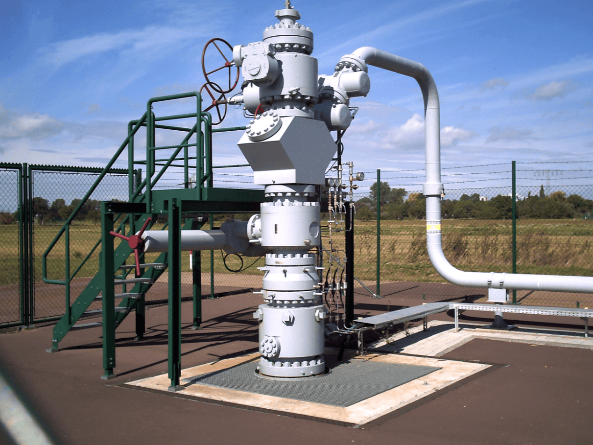
Pictures, photos, and images used are for illustration purposes and do not constitute any warranty or assertions on the suitability of use and should not be construed as an explicit or implicit recommendation or endorsement. All illustrations are given proper credit from our source of access and by their use here we do not specify or establish any copyright which belongs and stays unaffected with the existing copyright holder of that material.
References
- Wellhead – Wikipedia
- Investigating Sand Production Phenomena: An Appraisal of Past and Emerging Laboratory Experiments and Analytical Models
- Hydrocyclone technology for breaking consolidation and sand removal of the Natural gas hydrate
- Liquid Desander – Apex Flux Balancing (B-FSM069)
- Application of Multiphase Desander Technology to Oil and Gas Production

