Introduction
PVT analysis is performed to relate surface production to underground withdrawal for an oil reservoir and to simulate what takes place in the reservoir during production. PVT data have far-reaching applications in reservoir engineering, from estimating reserves to planning surface facilities to marketing crude.
Recent developments in improved oil technologies have increased the demand for extraction of non-traditional hydrocarbon deposits globally. Accurate PVT study is critical to ensure development of a profitable field – maximize production at the lowest cost.
Application
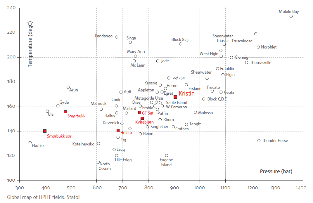
To meet growing demand for energy globally, oil companies have to explore reservoirs at extremely high pressure and temperature conditions. After discovery of a reservoir, the need to understand the amount of recoverable petroleum, the economic potential of the reservoir and the rates at which this resource can be produced is vital for both a low-cost shale field development as well as a multi-billion dollar offshore field.
In PVT studies, high quality density and viscosity data is crucial for determining accurate EOS (Equation of State) models, thermodynamic properties and transport equations. Integrated models using actual measurements from field (downhole GOR, viscosity, density) and lab (PVT: Formation volume factors, solution gas-oil ratio, viscosity, density) are used to predict crude oil flow properties and production rates, determine reservoir evaluations and determine pump type and sizes for land based operations. Viscosity and density data are an important factor in quality and marketability of produced oil, gas and condensates.

Problem Statement
New reservoirs are increasingly ultra-deep with very high pressure conditions (>25000 psi) and high temperature (>400 °F). It is very expensive to acquire sample fluids from ultra-deep wells so it is important that density and viscosity measurements be carried out with minimal volume of the reservoir fluid. Overall for PVT studies, density and viscosity measurements should be done:
- At HTHP (High Temperature High Pressure) conditions to reduce reservoir uncertainty
- With minimal volume of reservoir fluid
Process Challenges
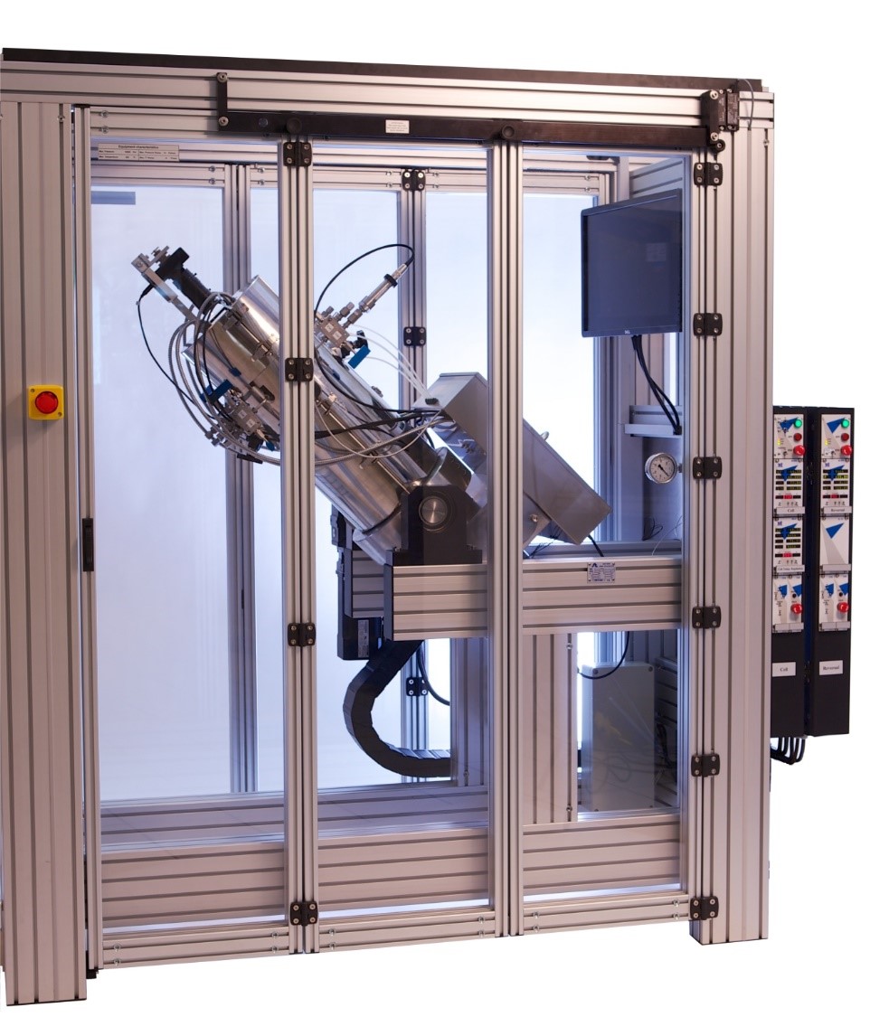
In PVT analysis, operators use either an offline or an inline instrument to measure density and another instrument to measure viscosity (mostly offline). There are major issues in using two separate instruments for measuring density and viscosity:
- Most traditional instruments used for density and viscosity measurement need separate fluid samples for analysis which are extracted from downhole fluid sample cylinders, using up large quantities of an extremely valuable fluid sample that cannot be reused in PVT
- Same temperature and pressure conditions are harder to achieve in two separate instruments leading to measurement errors
- Difficult to co-locate large, bulky density meters and viscometer inside PVT ovens due to space and mounting constraints
- Manual operation and needs long time for measurement
- Needs significant integration work in hardware and software to synchronize measurement data and ensure compliance
Rheonics' Proposition
Rheonics’ DVM is a single instrument combining HTHP density meter and viscometer that delivers simultaneous density, viscosity and temperature measurement in the harshest of conditions.

Operating Principle
The rheonics’ DVM measures viscosity and density by means of a torsional tuning fork resonator with flattened tine ends, which is immersed in the fluid under test. The more viscous the fluid, the higher the mechanical damping of the resonator, and the denser the fluid, the lower its resonant frequency. From the damping and resonant frequency, the density and viscosity may be calculated by means of rheonics’ proprietary algorithms. Thanks to rheonics’ coupled torsional resonator design (US patent number 9518906), the transducer is perfectly balanced, while maintaining excellent mechanical isolation from the sensor’s mounting. Damping and resonant frequency are measured by the rheonics sensing and evaluation electronics (US patent number 8291750). Based on rheonics’ proven gated phase-locked loop technology, the electronics unit offers stable and repeatable, high-accuracy readings over the full range of specified temperatures and fluid properties.

To know in detail about the technology of the rheonics’ torsional balanced resonators please refer to the whitepaper.
Robust built and superior sensor technology
Rheonics’ DVM sensors use patented balanced resonators to ensure consistent, reproducible measurements no matter how the DVM is mounted. DVM uses ultra-stable resonators, built using decades of experience in materials, vibrational dynamics and fluid-resonator interaction modelling that add up to the industry’s most robust, repeatable and well characterised sensors.
Single instrument, dual function
Rheonics’ DVM is a unique product that replaces two alternatives and offers better performance while operating at true reservoir conditions. It eliminates the difficulty of co-locating two different instruments along with the PVT cell in an oven or bath.


Accurate, fast and reliable measurements
Rheonics’ DVM are ultra-stable resonators. Sophisticated, patented 3rd generation electronics drive these sensors and evaluate their response. Great electronics, combined with comprehensive computational models, make the evaluation units one of the fastest and most accurate in the industry. DVM gives real time density and viscosity measurements in less than 2 seconds!

Widest operational capability
Rheonics’ extensive instrument capabilities enable users to carry out measurements in challenging reservoir conditions. It has the widest operational range in the market:
- Pressure range up to 30,000 psi
- Temperature range from -40 to 200°C
- Viscosity range: 0.02 to 300 cP
- Density range: 0 to 3 g/cc
Minimal sample size requirement
Minimal reservoir fluid is used for testing in the DVM since there is no requirement of a separate line or sampling system. Safe and cost-effective to operate, DVM requires only 0.7ml of sample to measure viscosity and density across the complete P,T range saving time and money.
Hassle free and convenient operation
DVM eliminates the need for separate instruments for measuring density and viscosity which call for appreciably larger sample volumes, numerous reconfigurations and cumbersome fluid transfer systems. It can continuously track change of viscosity and density of live oil sample across the complete run and does not require any hardware change or reconfiguration. Rheonics’ software is powerful, intuitive and convenient to use. Using no mercury, timer or multiple pistons, DVM is easy on the operations and environment.
Rheonics’ value proposition: The best in the industry
Very high pressures and temperatures, shocks and vibrations, limited availability of power and severe space constraints on drilling rigs call for novel approaches to measurement instruments. This serves as the charter for Rheonics’ DVM-PVT series of sensors. The following is a comparison of existing technologies of viscometers and density meters with Rheonics’ DVM ( torsional balanced resonator).
| Torsional Balanced Resonator (Rheonics DVM) | Electromagnetic moving piston | Vibrating tube density | Capillary Tubes | |
|---|---|---|---|---|
| Density Range | 0 – 3 g/cc | Cannot measure. | 0 – 3 g/cc | Cannot measure. |
| Density Accuracy | 0.001 g/cc | - | 0.0001 g/cc | - |
| Reproducibility | (0.0001 g/cc and better demonstrated) | - | (0.00001 g/cc for defined conditions) | - |
| Viscosity Range | 0.2 to 300 cP | 0.02 to 10,000 cP (needs 6 pistons) | Cannot measure. Needs to be calibrated to compensate for fluid viscosity. | 0.02 to 10,000 cP with multiple capillaries. |
| Viscosity Accuracy | 1% of actual | 1% of Full Scale | - | Depends on the accuracy of the time keeper. |
| Reproducibility | 0.5% of reading | 0.8% of reading | - | Depends on the accuracy of the time keeper. |
| Pressure rating Pressure influence | 0 to 30,000 psi (2000 bar) Fully compensated, No need for calibration. | 0 to 15,000 psi (1000 bar) Significant, user calibrated. | 0 to 1400 psi (100 bar), special to 6000 psi (400 bar) Significant, needs to be compensated. | Up to 15,000 psi |
| Temperature rating Temperature calibration | -40 to 200 °C Integrated temperature sensor in flow. Small mass of sensor. Isothermal conditions enable excellent accuracy. | Max. 190 °C Huge mass of sensor needs long time to reach isothermal conditions. Needs 40 min or higher for measurement. | Max. 150 °C Large mass of sensor. Significant influence on density measurement. At factory conditions, meets specs. Otherwise far worse. | Max. 200 °C Capillary tubes in oven or bath. Not easy to clean and fill. Needs long time to reach stable thermal conditions. |
| Flow condition Installation requirement Size | Static or flowing. No influence of flow rate. Small size (1.5” x 2” x 1.5”). Easy to integrate in PVT and core flood test setups. | Static or flowing (with adapter & valves). Not possible to integrate in PVT or core flood ovens. Generally used standalone. | Static or flowing. Vulnerable to pump noise and external vibration. Easy to integrate in PVT oven. | Static. Not possible to integrate in PVT oven. Used as a standalone instrument. |
| Price | $$ | $$$ | $$ - $$$ | $ - $$ |
| Installation cost | 0 to Low $ | Medium $$ | Medium $$ | Medium $$ |
| Maintenance | None required. | Needs extensive cleanup. | Regular calibration needed. | Frequent calibration & maintenance. |
| Lifetime cost to customer | $$ | $$$$$ | $$$$$$ | $$$$ |
| Typical measurement issues | Low viscosities below 0.2 cP are measurable but not calibrated currently. | Hard to integrate in a flow loop. Pressure introduces high error. Needs extensive calibration. | Lack of viscosity measurement. Needs recalibration with reference fluid under test pressure with similar viscosity as the sample fluid. | Manual measurements. No flow through. No density measurement. |
Electronics built to fit your needs
Available in both an explosion-proof transmitter housing and a small-form factor DIN rail mount, the sensor electronics enables easy integration into process pipelines and inside equipment cabinets of machines.


Easy to integrate
Multiple Analog and digital communication methods implemented in the sensor electronics makes connecting to industrial PLC and control systems straightforward and simple.
Implementation
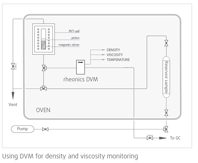
Directly install the sensor to your process stream to do real time viscosity and density measurements. No bypass line is required: the sensor can be immersed in-line, flow rate and vibrations do not affect the measurement stability and accuracy. Optimize PVT studies by providing repeated, consecutive, and consistent tests on drilling fluids.
Rheonics Instrument Selection
Rheonics designs, manufactures and markets innovative fluid sensing and monitoring systems. Precision built in Switzerland, Rheonics’ in-line viscometers has the sensitivity demanded by the application and the reliability needed to survive in a harsh operating environment. Stable results – even under adverse flow conditions. No effect of pressure drop or flow rate. It is equally well suited to quality control measurements in the laboratory. No need to change any component or parameter to measure across full range.
Suggested product(s) for the Application
- Simultaneous density and viscosity measurement
- Measure at reservoir conditions: 30,000 psi and 400°F.
- On the bench or in the field
- Accurate measurement in the harshest of conditions
- 5 minutes from box to operation in your flow loop
- Built in fluid temperature measurement

