Density and viscosity are critical parameters in 3D cement printing as they directly affect the printability, structural integrity, and layer adhesion of the printed material. Inline monitoring of this parameters are key for a robust real-time control and to ensure quality.
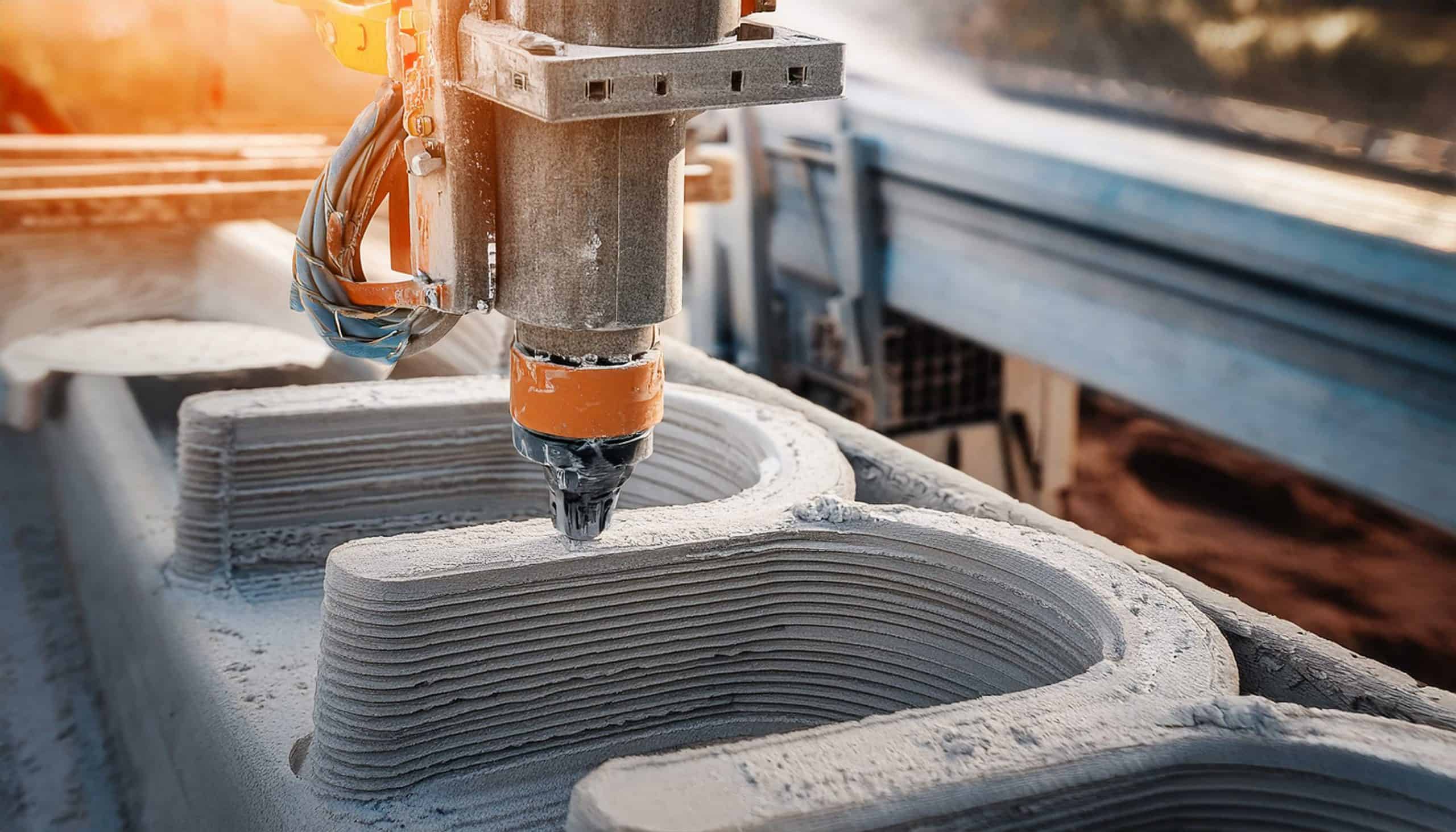
Figure 1: 3D Cement Printing [1]
Table of Content
- Introduction
- Cement Additive Manufacturing Process
- Process and Monitoring Challenges
- Rheonics Inline Density and Viscosity Sensors
1. Introduction
Additive manufacturing has made significant progress over the years and has reached relevance in different industries like 3D cement or concrete printing (3DCP). Also known as concrete additive manufacturing, this is a cutting-edge technology that enables an automated layer-by-layer construction of structures using cementitious materials. Unlike traditional concrete construction, which requires formwork and huge manual labor, 3D printing directly extrudes cement-based mixtures following a pre-programmed digital model, not so different from well-known polymer 3D printings. Different technologies of 3DCP are possible, like binder jetting and material jetting, but extrusion is the predominant method. This technology offers several advantages, including reduced material waste, faster construction times, and greater design flexibility. To achieve this, however, it is key to monitor and optimize the material composition, extrusion parameters, and curing conditions to ensure uniform printability, material consistency, correct bonding between layers, environmental control, etc.
This article highlights the relevance of key parameters like viscosity and density in 3D cement printing and how Rheonics sensors enable real-time inline measurement for monitoring and control.
PERI 3D Construction Printing: First 3D-printed residential building in Germany – [1]
2. Cement Additive Manufacturing Process
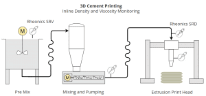
Figure 2: 3D Cement Printing Process Overview
In a broad view, a process of 3D cement printing can be divided in the following steps [2]:
Pre mix
Pre-dosing materials are mixed to obtain cement specially developed for 3DCP. This generally includes cement, sand, additives and sometimes fibers to improve strength and workability. Several companies already offer this premixed material ready for 3D cement printing. Initial developments used thickening agents to ensure a high yield stress after extrusion, while recent developments use retardants to prevent the setting of the fresh material during the pumping process, in combination with accelerators that counteract the retardant effect and induce faster setting times.
Mixing
Hydration process of the dry material by mainly adding water. Mixing can be either done by batches or through a continuous process. Some process use a second mixing phase right before the extrusion for different purpose related to the fluid used.
Transport
The transport of concrete normally requires the use of progressive cavity pumps, one can also find positive displacement piston pumps being used here. A consistent supply of fresh concrete material is essential for any successful printing operation. Generally, the intention is to avoid frequent stops in the printing and that the speed does not exceeds the maximum vertical build rate of the material.

Figure 3: Progressive cavity pumps [3]
Extrusion is the critical step in 3D cement printing and consists of extruding the material through a nozzle or die mounted in a robotic arm or gantry system capable of moving normally in 3 directions and follows a pre-programmed digital model. Each layer bonds with the previous one, gradually building up the structure. Nozzles can either be passive nozzles or controlled deposition screw nozzles. The former achieves extrusion by the transport pumping system itself, while the latter features an open hopper with a feeder screw to extrude the material directly allowing higher precision in the flow control.
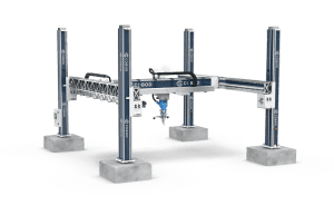
Figure 4: Gantry system for cement printing extrusion [4]
3. Process and Monitoring Challenges
The fluid behavior of concrete sets many challenges in the monitoring of its rheology properties. Concrete has a yield stress, meaning that it behaves as a solid below certain shear stress applied to it, and a fluid behavior when this shear stress is exceed. Additionaly, there is a clear necessity for high flowability during pumping but also high stiffness and certain strength to hold its shape after extrusion.
Viscosity indicates a fluid’s resistance to flow as well as its consistency, while density is used as an indicative of the fluid’s homogeneous mixing (e.g. water to cement ratio) that influences the strength, printability, and setting time. Generally viscosity and density monitoring is required to determine:
- Printability (retained shape after deposition, number of layers supported)
- Material strength
- Print quality
- Drying shrinkage
- Avoid jamming on extruder
In addition to material properties monitoring, knowing the printing parameters and curing conditions are key in the 3D concrete printing process.
4. Rheonics Inline Density and Viscosity Sensors
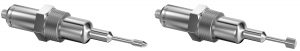
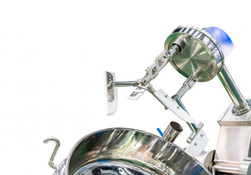
Figure 5: Rheonics Inline Viscometer (SRV) and Density and Viscosity Meter (SRD) long insertion variant with threaded connection NPT 1.25”
Rheonics offers inline process density and viscosity meters for real-time monitoring of concrete.
Rheonics SRV Inline Viscometer: This sensor measures a wide range of viscosity and temperature in real-time and is suitable for installation in tanks to monitor mixing processes and in pipelines for continuous measurement of flowing fluid. Rheonics SRV is specially suited for high speed mixing processes and is unaffected by presence of bubbles in the fluid or external vibrations.
Rheonics SRD Inline Density and Viscosity Meter: This sensor measures density, viscosity and temperature in real time. It is best suited for installation in pipelines and tanks with a constant mixing speed. SRD adds density to the measurements, allowing further fluid concentration calculations, however, has a narrower measurement viscosity range compared to the SRV and high concentration of bubbles can add noise to readings due to the density measurement. SRD is not affected by external vibrations.
Multiple SRV and SRD (Type-SR) sensor probes are offered to suit specific installation requirements. Visit SRV Viscometer Variants and SRD Density and Viscosity Meter Variants.
Installation
Concrete is a granular fluid composed of liquid, mainly water added during mixing, and usually fine particles like silica fume, fly ash, slag, etc. Due to its composition and common abbrasive properties, Rheonics has the next installation requirements to measure viscosity and density of concrete with the Type-SR sensors.
- Installation in Sweep Elbow
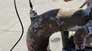
Figure 6: SRD Density and Viscosity Meter elbow installation example
Rheonics sensor long insertion probes (Type-SR-X5) in an elbow installation is a very good solution for concrete inline measurements. An elbow installation allows the fluid to come parallel or axial to the sensor probe’s sensing element, while the long insertion design places the sensing element further in the line where fluid’s flow is more consistent than near the wall. This ensures that the sensing element stays always clean (flow keeps it clean and free of any deposits).
With a long insertion probe, the client can define the insertion length (A) and process connection (B). Next table shows a common solution using a threaded connection NPT 1.25” and a elbolet.
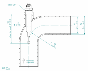
Figure 7: SRD Density and Viscosity Meter elbow installation drawing
Find more installation examples in sweep elbows in our article: Installing Type-SR Viscosity and Density Meters in Sweep Elbows
- Installation with Rheonics Stargate
The SRV or SRD Stargate (SG) variant is suited for high-viscous and high-speed fluids minimizing deposits and loads on the probe, as it has a wafer cell design that places the probe centered in a straight line.
The advantage of the Stargate installation is that it will have the least amount of fouling and can reduce the abrasion on the probe. Main consideration for this installation is the requirement of adapters to connect to the process. Rheonics offers Tri-Clamp adapters which are generally not suited for cement or concrete applications. For this reason, client should follow the mechanical interface drawings of the Stargate to adapt it to the process.
- Perpendicular Installation
A perpendicular installation places the probe at 90° from the fluid’s flow. The main advantage of this installation is it’s simplicity. Normally, a Rheonics sensor probe with threaded connection (G1/2 or NPT 3/4”) is used and a weldolet required for installation (HAW-12G-OTK or WOL-34NL). This can be suitable for installations after mixing, between hoses, or right before the extrusion die or print head.
This installation, however, is prone to deposits or accumulations around the probe that can cover the sensing element and thus affect the sensor readings. Fluid deposits are common for high viscosity fluids like cement or concrete. Client should make sure to avoid zones prone to deposits (dead zones), and to clean the probe if deposits are formed.
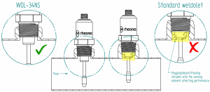
Figure 8: Short sensor probe perpendicular installation in straight line
5. Considerations on installation
Abrasion by Erosion
Concrete applications can expose the sensor probes to abrasion due to the erosion effects of the fluid on the probe’s surface material. In these cases, probes would need replacement after certain time. Users only needs to request a new probe, while the sensor cable and electronics are kept on place. Probe’s lifespan in these conditions depend on flow rate, particles in the fluid, duty cycle, etc. This is not possible to estimate in advance but Rheonics sensors can be configured to show users the level of abrasion and warn when a replacement is required.
Wetted Material
Rheonics sensor probes for cement are offered in Stainless Steel 316L material. Learn more on probe materials here: Rheonics viscometer density material chemical compatibility
Flow speed limit
Rheonics SRV and SRD probes are compatible with flow speeds up to 10 m/s. Parallel installation in elbow reduces the impact of flow speed on the probes but speeds in this range can still add too much noise to readings. Read more on Type-SR probes with high viscosity and speed fluids.
Particles in fluid
The presence of particles in the measured fluid is linked to the abrasion effects on the probe. Normally, soft particles in the order of microns don’t affect the sensor measurement. These may only impose noise in the readings that can be filtered by the sensor electronics. Bigger or hard particles in the order of milimeters or centimeters can create very high level of noise in the readings or even damage the probe, thus these particles must be avoided.
References
[1] PERI 3D Construction Printing: First 3D-printed residential building in Germany (EN)
[2] https://kth.diva-portal.org/smash/get/diva2:1814422/SUMMARY01.pdf
[3] PCM EcoMoineau™ C multi-application stainless steel progressive cavity pump
[4] Solution | COBOD International
[5] https://www.sciencedirect.com/science/article/pii/S2452321618300714